Eureka AIR delivers breakthrough ideas for toughest innovation challenges, trusted by R&D personnel around the world.

Air draft dedusting device of feeding position of ring cooling machine

A technology of dust removal device and ring cooler, which is applied in the direction of furnace control device, treatment of discharged materials, furnace, etc., to achieve the effect of ensuring dust removal effect, long life and improving working environment

Active Publication Date: 2017-05-24
MCC NORTH (DALIAN) ENG TECH CO LTD
View PDF6 Cites 0 Cited by
  • Summary
  • Abstract
  • Description
  • Claims
  • Application Information

AI Technical Summary

Problems solved by technology

[0005] In order to solve the problem that the partitions in the prior art cannot effectively solve the problem that the dust removal air intake has an adverse effect on the high temperature air intake, and the dust will pass through the gap between the trolley and the fume hood, the horizontal section between the fume hood and the material guide chute To solve the problem of overflow in the gap between them, the embodiment of the present invention provides a suction and dust removal device for the material receiving point of the annular cooler. , door shaft bearing, limit angle steel and heat insulation dust cover;

Method used


Image

  • Air draft dedusting device of feeding position of ring cooling machine
  • Air draft dedusting device of feeding position of ring cooling machine
  • Air draft dedusting device of feeding position of ring cooling machine

Examples


Embodiment Construction

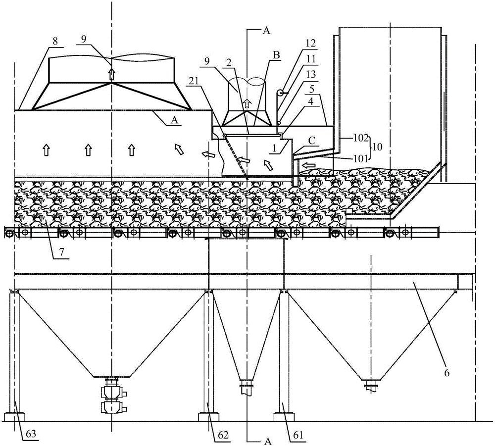
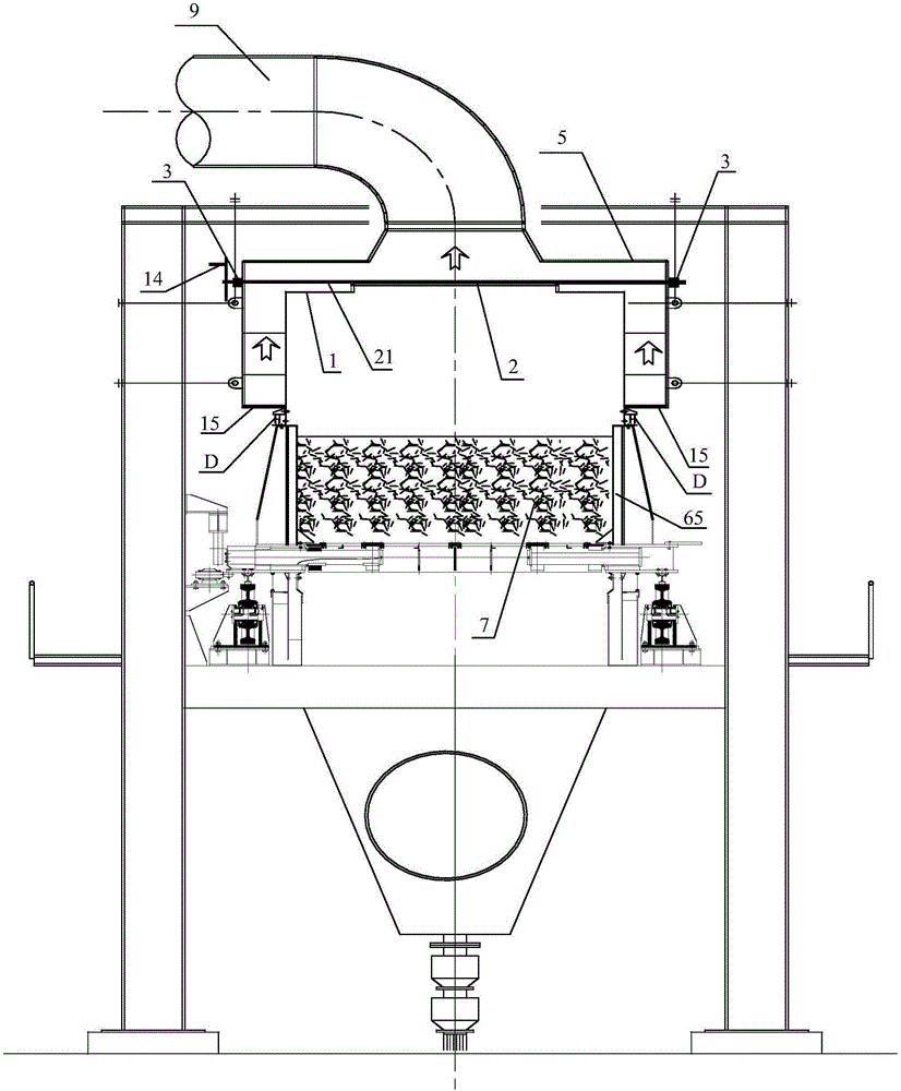
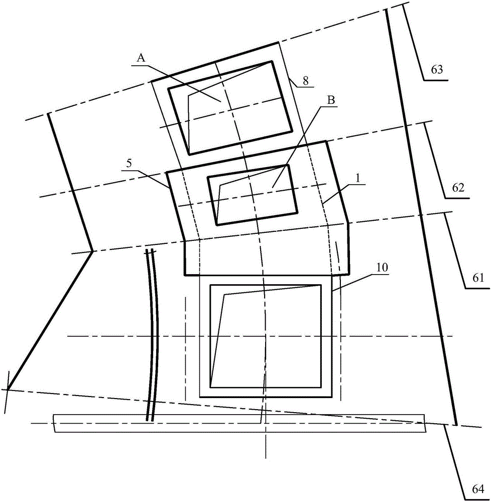
[0029] In order to solve the problem that the partitions in the prior art cannot effectively solve the problem that the dust removal air intake has an adverse effect on the high temperature air intake, and the dust will pass through the gap between the trolley and the fume hood, the horizontal section between the fume hood and the material guide chute Problems with gap overflow between, such as figure 1 shown, and see figure 2 and image 3 The embodiment of the present invention provides a suction and dust removal device for the material receiving point of the annular cooler. The suction and dust removal device for the material receiving point of the annular cooler includes: a first fume hood 1, an adjusting baffle door 2, a door shaft bearing 3, Limiting angle steel 4 and adiabatic dust cover 5;

[0030] The first fume hood 1 is covered above the sintered mineral material 7 between the second axis 61 and the third axis 62 of the annular cooler 6, and the first fume hood 1 ...


PUM


Abstract

The invention discloses an air draft dedusting device of a feeding position of a ring cooling machine. The air draft dedusting device of the feeding position of the ring cooling machine comprises a first smoke cover, an adjustable baffle door, door shaft bearings, a limiting angle steel and a heat insulation dedusting cover; the first smoke cover is installed above sintering minerals between the second axis and the third axis of the ring cooling machine in a covering mode, a second smoke cover is installed above sintering minerals between the third axis and the fourth axis of the ring cooling machine in a covering mode, and a high-temperature air draft port is formed in the second smoke cover; the heat insulation dedusting cover is installed above horizontal segments of the first smoke cover and a guiding chute in a covering mode, a dedusting air draft port is formed in the heat insulation dedusting cover, and the adjustable baffle door is installed on the first smoke cover; and an installation hole is formed in the heat insulation dedusting cover, a door shaft of the adjustable baffle door penetrates through the installation hole, and the two ends of the door shaft are sleeved with the door shaft bearings; and the door shaft bearings are located outside the heat insulation dedusting cover, and when the adjustable baffle door is closed, the adjustable baffle door is clamped into the limiting angle steel. According to the air draft dedusting device of the feeding position of the ring cooling machine, the dedusting effect can be guaranteed, and usable heat can be directly draught away by the dedusting air draft port.

Description

technical field [0001] The invention relates to the technical field of dust removal for annular coolers, in particular to a suction and dust removal device for a material receiving point of an annular cooler. Background technique [0002] The sintered material burned by the sintering machine will enter the material receiving point area of ​​the annular cooler through the material guide chute, and then be transported forward with the trolley of the annular cooler, and the cooling will be realized during the transportation. During the cooling process of the sintered ore material by the machine, waste heat will be generated. In order to save energy, the waste heat will be collected for waste heat utilization. Among them, the temperature of the sintered ore material falling into the receiving point of the ring cooler is the highest. A high-temperature air intake is set at the material receiving point to collect the heat of the sintered material at the material receiving point. A...

Claims


Application Information

Patent Timeline
Patent Type & Authority Applications(China)
IPC IPC(8): F27D15/02F27D17/00F27D19/00
CPCF27D15/02F27D17/001F27D17/008F27D19/00F27D2019/0059Y02P10/25
Inventor 杨肇博王博闻刘冠男
Owner MCC NORTH (DALIAN) ENG TECH CO LTD
Why Eureka
Eureka Blog
Learn More