
Airplane hanging point position detection device

A technology of lifting point position and detection device, applied in the direction of mechanical measuring device, measuring device, adopting mechanical device, etc., can solve the problems of complex operation, time-consuming data processing, high requirements for test environment, etc., and achieve simple operation and low manufacturing cost , the effect of low objective conditions

Active Publication Date: 2017-05-24
AECC SHENYANG ENGINE RES INST
View PDF12 Cites 4 Cited by
  • Summary
  • Abstract
  • Description
  • Claims
  • Application Information

AI Technical Summary

Problems solved by technology

Aircraft hanging point position detection usually refers to the coaxiality measurement of the same side of the aircraft hanging point, and the distance measurement of different measurement hanging points. The traditional detection of the aircraft hanging point position is usually completed by laser tracker electronic equipment. The tracker is expensive and complicated to operate. The instrument has high requirements for the test environment and data processing is time-consuming.

Method used


Image

  • Airplane hanging point position detection device
  • Airplane hanging point position detection device
  • Airplane hanging point position detection device

Examples


Embodiment Construction

[0029] In order to make the objectives, technical solutions and advantages of the present invention clearer, the technical solutions in the embodiments of the present invention will be described in more detail below in conjunction with the drawings in the embodiments of the present invention. In the drawings, the same or similar reference numerals denote the same or similar elements or elements having the same or similar functions throughout. The described embodiments are some, but not all, embodiments of the invention. The embodiments described below by referring to the figures are exemplary and are intended to explain the present invention and should not be construed as limiting the present invention. Based on the embodiments of the present invention, all other embodiments obtained by persons of ordinary skill in the art without creative efforts fall within the protection scope of the present invention. Embodiments of the present invention will be described in detail below ...


PUM


Abstract

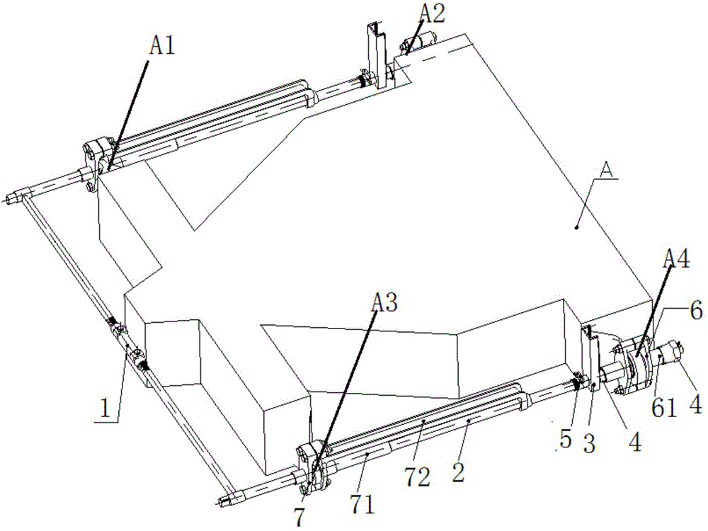
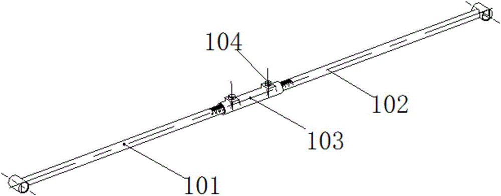
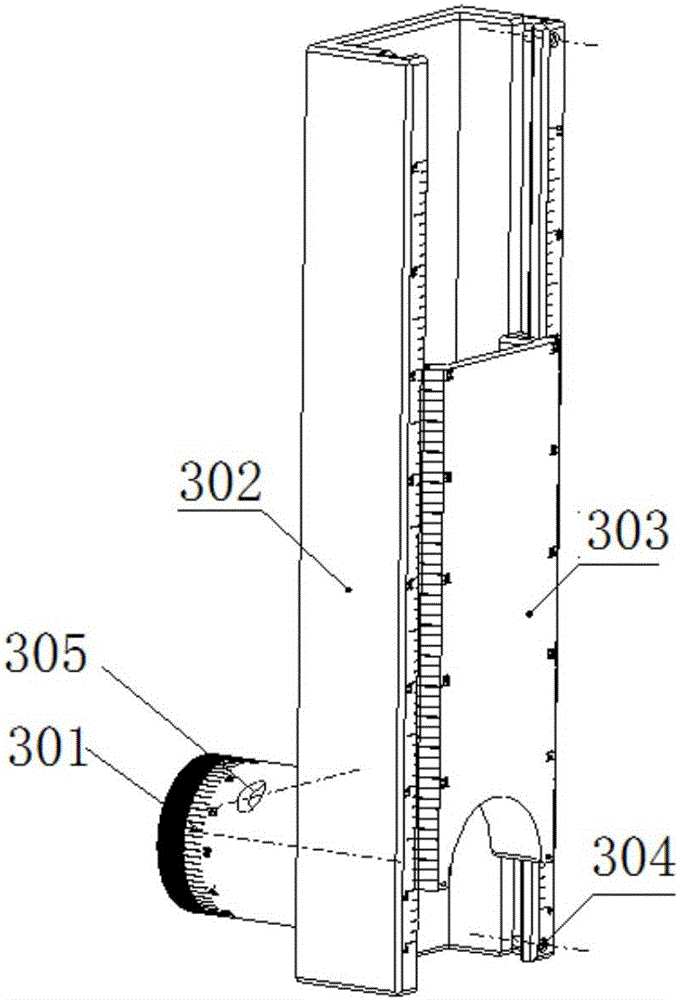
The invention discloses an airplane hanging point position detection device, and belongs to the field of test and measurement designs. The detection device comprises a cross shaft component, long shafts, a sliding bush component and a short shaft component. The transverse spacing of hanging points is measured by inserting one end of each of two long shafts into a left hanging point and a right hanging point respectively, inserting the other end of each of the two long shafts into transverse adjusting shafts on two sides of a transverse adjusting shaft component respectively, and reading the spacing between the left hanging point and the right hanging point by using scales on the transverse adjusting shaft component, and the depths of the long shafts inserted into the hanging points are adjusted to achieve an aim of avoiding obstacles between the hanging points. The coaxiality of the hanging points is measured by inserting the long shafts into front hanging points, inserting short shafts into back hanging points, and connecting the sliding bush component with two shafts. During measurement, the top ends of the short shafts are laminated with a sliding bush, the position of a slotted sliding block of the sliding bush component on the sliding bush and the angles between the sliding bush component and the long shafts are adjusted to ensure that a semicircular surface of the lower part of the slotted sliding block is laminated with a short shaft, and coaxiality deviation data of front and back hanging points is read by using scales. The detection device disclosed by the invention has relatively low requirements on objective conditions including an operating space, a measurement environment and the like, is simple to operate, and can obtain measurement data in real time.

Description

technical field [0001] The invention belongs to the field of test measurement design, and in particular relates to a position detection device for an aircraft suspension point. Background technique [0002] The thrust reverser is connected to the aircraft through the hanging point of the aircraft pylon. Therefore, it is necessary to measure and verify the accuracy of the hanging point of the pylon. Aircraft hanging point position detection usually refers to the coaxiality measurement of the same side of the aircraft hanging point, and the distance measurement of different measurement hanging points. The traditional detection of the aircraft hanging point position is usually completed by laser tracker electronic equipment. The tracker is expensive and complicated to operate. The instrument has high requirements on the test environment and data processing is time-consuming. Due to the particularity of the operating environment of the aircraft pylon, a convenient, easy-to-oper...

Claims


Application Information

Patent Timeline
IPC IPC(8): G01B5/14G01B5/252
CPCG01B5/14G01B5/252
Inventor 廉正彬刘洪波杜鑫谭征岳田琦楠
Owner AECC SHENYANG ENGINE RES INST
Learn More