Eureka AIR delivers breakthrough ideas for toughest innovation challenges, trusted by R&D personnel around the world.

Locking device for power transmission line detector

A locking device and transmission line technology, which is applied to measuring devices, parts of electrical measuring instruments, casings of measuring devices, etc., can solve the problems of cumbersome and laborious loading and unloading of detectors, and achieve easy control and structure of locking and disengaging Simple and reasonable design

Pending Publication Date: 2017-05-24
TIANJIN ZHILIAN HENGXIN ELECTRIC POWER EQUIP CO LTD
View PDF4 Cites 7 Cited by
  • Summary
  • Abstract
  • Description
  • Claims
  • Application Information

AI Technical Summary

Problems solved by technology

The above-mentioned structure does not exist in the prior art, resulting in very cumbersome and laborious loading and unloading of the detector to the transmission line, requiring other auxiliary devices for auxiliary construction

Method used


Image

  • Locking device for power transmission line detector

Examples


Embodiment Construction

[0012] In order to further understand the content of the invention, features and effects of the present invention, the following examples are given in detail as follows:

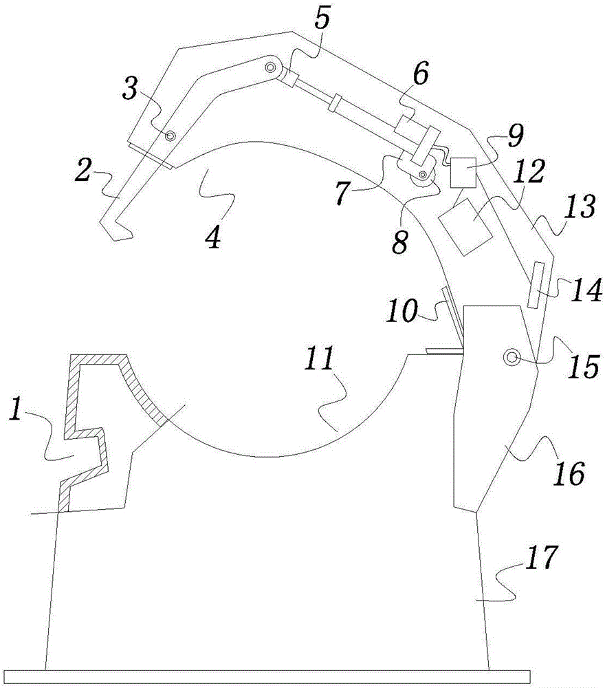
[0013] See figure 1 , the locking device for the transmission line tester of the present invention comprises an upper housing 13 with an upper notch 4 at the bottom and a lower housing 17 with a lower notch 11 at the top, the upper housing 13 and the lower housing 17 After the two are snapped together, a channel for the transmission wire to pass is formed between the upper notch 4 and the lower notch 11 .

[0014] A bayonet 1 is provided on the side wall of the front part of the lower housing 17, two opposite side ear plates 16 are provided on the side wall of the rear part of the lower housing 17, and the rear part of the upper housing 13 passes through the second The hinge shaft 15 is hingedly connected between the tops of the two side ear plates 16, and the second hinge shaft 15 is provided with a torsio...


PUM


Abstract

The invention relates to a locking device for a power transmission line detector. The locking device comprises an upper-part shell and a lower-part shell, wherein the bottom part of the upper-part shell is provided with an upper concave opening, and the top part of the lower-part shell is provided with a lower concave opening; a clamping opening is arranged on the side wall of the front part of the lower-part shell; two opposite side ear plates are arranged on the side wall of the rear part of the lower-part shell; the rear part of the upper-part shell is hinged between the top parts of the two side ear plates by a second hinging shaft; a torsion spring is arranged on the second hinging shaft; a clamping hook is hinged at the front part of an inner cavity of the upper-part shell by a first hinging shaft; the front end of the clamping hook extends out of an opening at the front end of the upper-part shell; a base is arranged at the middle part of the inner cavity of the upper-part shell; a rotary base is hinged on the base; a pushing rod motor is fixed on the rotary base; a rotary connection block is arranged at the front end of a telescopic rod of the pushing rod motor; and the rotary connection block is hinged with the inner end of the clamping hook. The locking device also comprises a control circuit board, a battery and a Hall sensor, wherein the pushing rod motor, the battery and the Hall sensor are respectively and electrically connected with the control circuit board.

Description

technical field [0001] The invention belongs to the technical field of power fault detection, and in particular relates to a locking device for a power transmission line detector. Background technique [0002] As an important infrastructure for the national economy and the people's livelihood, power transmission lines are particularly important to ensure their safe operation. Due to natural factors and human factors, transmission lines usually have various faults, such as open circuit caused by disconnection of transmission line, short circuit of transmission line to ground, short circuit between phase lines, etc. It is very important to find and deal with the above faults in time . The existing fault indicators use the principle of current transformers, take the transmission line as the primary winding, install the annular iron core wound with the secondary winding on the indicator, detect the power supply of the line through the induced potential of the secondary winding,...

Claims


Application Information

Patent Timeline
IPC IPC(8): G01R31/08G01R1/04
CPCG01R1/04G01R1/0408G01R31/085
Inventor 崔大鹏薄立华
Owner TIANJIN ZHILIAN HENGXIN ELECTRIC POWER EQUIP CO LTD
Why Eureka
Eureka Blog
Learn More