System-on-chip bus behavior detection method and apparatus
A system-on-chip and detection method technology, applied in the field of system-on-chip, can solve problems such as single function of the monitoring module, inability to capture AXI bus data, and inability to meet the diverse needs of SoC chips, so as to achieve the effect of meeting diverse needs
- Summary
- Abstract
- Description
- Claims
- Application Information
AI Technical Summary
Problems solved by technology
Method used
Image

Examples
no. 2 example
[0133] In order to better illustrate the purpose of the present invention, further illustrations are given on the basis of the first embodiment of the present invention.
[0134] Figure 7 It is a schematic diagram of the application scene of the second embodiment of the SoC bus behavior detection method of the present invention, as Figure 7 As shown, the processor 700 represents a master device, and data transmission is performed between the processor 700 and the slave device 701 through the AXI bus / ACE bus; The behavior of the bus is detected, and the DDR memory 703 is used to store the bus behavior detection result obtained by the detector. The detector 702 is connected to the AXI bus / ACE bus through the slave interface for monitoring the AXI bus / ACE bus; the detector 702 is connected to the DDR memory 703 through the master interface, and the monitoring of the AXI bus / ACE bus by the detector 702 belongs to non-intrusive monitoring. Therefore there is no interference wit...
no. 3 example
[0163] For the method of the embodiment of the present invention, the embodiment of the present invention also provides a SoC bus behavior detection device.
[0164] Figure 10 It is a schematic diagram of the first component structure of the SoC bus behavior detection device in the embodiment of the present invention, such as Figure 10 As shown, the device includes: a receiving module 1000 and a detecting module 1001; wherein,
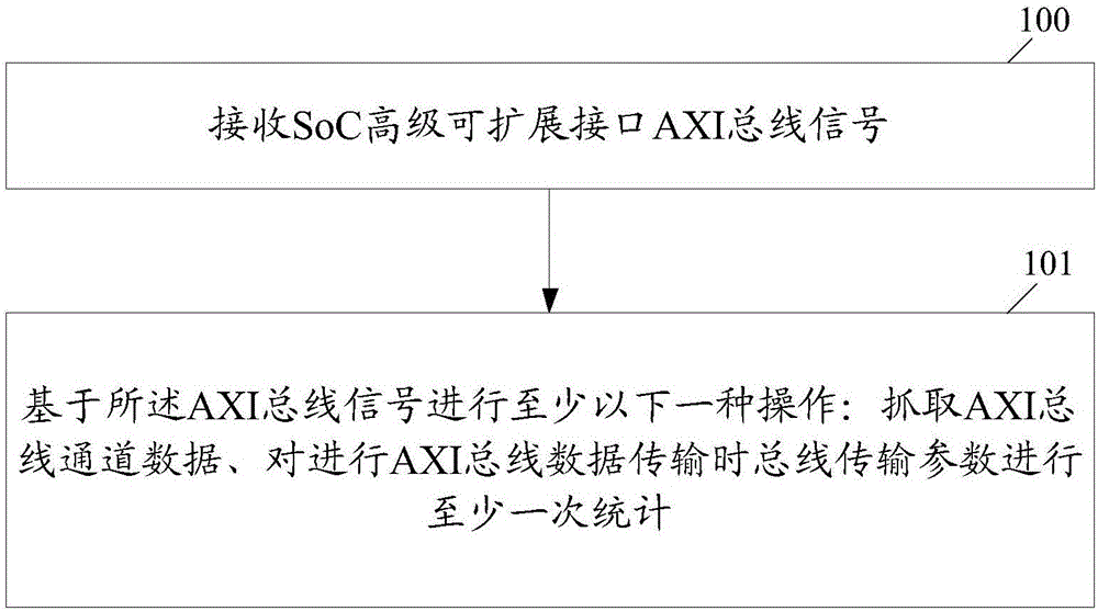
[0165] The receiving module 1000 is used to receive the SoC advanced extensible interface AXI bus signal; the detection module 1001 is used to perform at least one of the following operations based on the AXI bus signal: grabbing AXI bus channel data, and performing AXI bus data transmission to the bus Transmission parameters for statistics;
[0166] And / or, the receiving module 1000 is configured to receive the AXI conformance extended ACE bus signal in the SoC bus signal; the detection module 1001 is configured to capture ACE bus channel data bas...
no. 4 example
[0179] In order to better reflect the purpose of the present invention, further illustrations will be made on the basis of the third embodiment of the present invention.
[0180] Figure 11 It is a schematic diagram of the second component structure of the SoC bus behavior detection device in the embodiment of the present invention, as Figure 11 As shown, the device includes: a first timing adjustment unit 1100, a second timing adjustment unit 1101, an AXI bus detection unit 1102, an ACE bus detection unit 1103, a statistics unit 1104, a configuration unit 1105, a first clearing unit 1106, a second clearing unit unit 1107, data transmission unit 1108 and third timing adjustment unit 1109; wherein,
[0181] The configuration unit 1105 is used to configure the parameters of the bus data capture and the statistical parameters of the bus transmission parameters, send the parameters of the configured bus data capture to the AXI bus detection unit / ACE bus detection unit, and trans...
PUM
 Abstract
Description
Claims
Application Information
 - Generate Ideas
- Intellectual Property
- Life Sciences
- Materials
- Tech Scout
- Unparalleled Data Quality
- Higher Quality Content
- 60% Fewer Hallucinations
Browse by: Latest US Patents, China's latest patents, Technical Efficacy Thesaurus, Application Domain, Technology Topic, Popular Technical Reports.
© 2025 PatSnap. All rights reserved.Legal|Privacy policy|Modern Slavery Act Transparency Statement|Sitemap|About US| Contact US: help@patsnap.com