Full-automatic mutual inductor magnetic core strip winding device

A winding device and transformer technology, which is applied in transformer/inductor magnetic core, inductor/transformer/magnet manufacturing, magnetic core manufacturing, etc., can solve low work efficiency, high labor intensity, and increase the screening workload of quality control links and other issues to achieve the effect of improving production efficiency, reducing labor intensity, and reducing screening workload

Active Publication Date: 2017-05-24
江苏二互电气有限公司
View PDF5 Cites 19 Cited by
  • Summary
  • Abstract
  • Description
  • Claims
  • Application Information

AI Technical Summary

Problems solved by technology

Winding magnetic cores with amorphous alloy strips is a relatively advanced preparation method for transformer cores. Amorphous alloy strips are usually prepared by single-roll quick quenching method: first, the amorphous alloy strips need to be put into the furnace Carry out melting and calcination, then pour the fully fused amorphous alloy solution onto a cooling roll that rotates rapidly and has a lower surface temperature, the molten amorphous alloy material contacts the cooling roll and cools rapidly to form an amorphous alloy strip, and then the amorphous alloy The alloy strip is wound into a closed ring shape. The conventional amorphous alloy strip winding is mainly automatic mechanical...

Method used


Image

  • Full-automatic mutual inductor magnetic core strip winding device
  • Full-automatic mutual inductor magnetic core strip winding device

Examples


Embodiment Construction

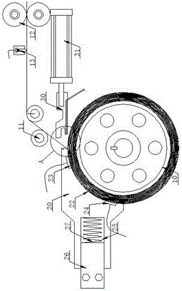
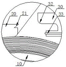
[0017] refer to Figure 1 to Figure 2 , Figure 1 to Figure 2 It is a structural schematic diagram of a specific embodiment of the present invention.

[0018] Such as Figure 1 to Figure 2 As shown, a fully automatic transformer magnetic core strip winding device includes a transformer magnetic core winding roller 10, the axis of the transformer magnetic core winding roller 10 is horizontally arranged, and the transformer magnetic core winding The top of the winding roller 10 is provided with a magnetic core winding and cutting fixed block 20 and a magnetic core winding and cutting movable block 30, one end of the magnetic core winding and cutting fixed block 20 is fixedly arranged, and the magnetic core winding and cutting fixed block 20 The other end of the transformer core winding roller 10 is facing the roller surface, and the magnetic core winding and cutting fixing block 20 is provided with a magnetic core strip fixed on the top surface of one end of the transformer co...


PUM


Abstract

The invention discloses a full-automatic mutual inductor magnetic core strip winding device. The device comprises a mutual inductor magnetic core winding roll, a magnetic core winding cutting fixed block and a magnetic core winding cutting movable block, wherein a magnetic core strip fixed cutting disc is arranged at the top of one end, toward the mutual inductor magnetic core winding roll, of the magnetic core winding cutting fixed block; a magnetic core strip movable cutting disc is arranged at the end, toward the magnetic core strip fixed cutting disc, of the magnetic core winding cutting movable block and is matched with the magnetic core strip fixed cutting disc; a strip winding arc inductive face is arranged on the magnetic core winding cutting fixed block, and faces the surface of the mutual inductor magnetic core winding roll; an upper winding terminal inductor and a lower winding terminal inductor are respectively arranged at the upper end and the lower end of the strip winding arc inductive face. The device can be used for cutting of a continuous mutual inductor magnetic core strip and adhering the mutual inductor magnetic core strip to the magnetic core roll surface, and can accurately determine the quantitative winding terminal of the mutual inductor magnetic core strip.

Description

technical field [0001] The invention relates to the technical field of production of a transformer non-gold alloy magnetic core material, in particular to a fully automatic transformer magnetic core strip winding device. Background technique [0002] The structure of transformers widely used in modern industry is mainly composed of mutually insulated primary windings, secondary windings, magnetic cores, frames, shells, terminals and other components. Winding magnetic cores with amorphous alloy strips is a relatively advanced preparation method for transformer cores. Amorphous alloy strips are usually prepared by single-roll quick quenching method: first, the amorphous alloy strips need to be put into the furnace Carry out melting and calcination, then pour the fully fused amorphous alloy solution onto a cooling roll that rotates rapidly and has a lower surface temperature, the molten amorphous alloy material contacts the cooling roll and cools rapidly to form an amorphous al...

Claims


Application Information

Patent Timeline
IPC IPC(8): H01F41/02H01F27/25
CPCH01F41/022
Inventor 丁鸿飞
Owner 江苏二互电气有限公司
Why Eureka
Try Eureka