
Cooling chambers and semiconductor processing equipment

A cooling cavity and processed technology, applied in the field of microelectronics, can solve problems such as film quality deterioration, low equipment productivity, wafer breakage, etc., and achieve the effect of avoiding wafer breakage or film quality deterioration or equipment productivity.

Active Publication Date: 2019-07-05
BEIJING NAURA MICROELECTRONICS EQUIP CO LTD
View PDF4 Cites 0 Cited by
  • Summary
  • Abstract
  • Description
  • Claims
  • Application Information

AI Technical Summary

Problems solved by technology

[0007] In order to solve the above problems, the present invention provides a cooling chamber and semiconductor processing equipment, which can avoid the problems of wafer cracking or film quality deterioration or low equipment productivity caused by too fast or too slow cooling speed

Method used


Image

  • Cooling chambers and semiconductor processing equipment
  • Cooling chambers and semiconductor processing equipment
  • Cooling chambers and semiconductor processing equipment

Examples


Embodiment Construction

[0029] In order for those skilled in the art to better understand the technical solution of the present invention, the cooling chamber and semiconductor processing equipment provided by the present invention will be described in detail below with reference to the accompanying drawings.

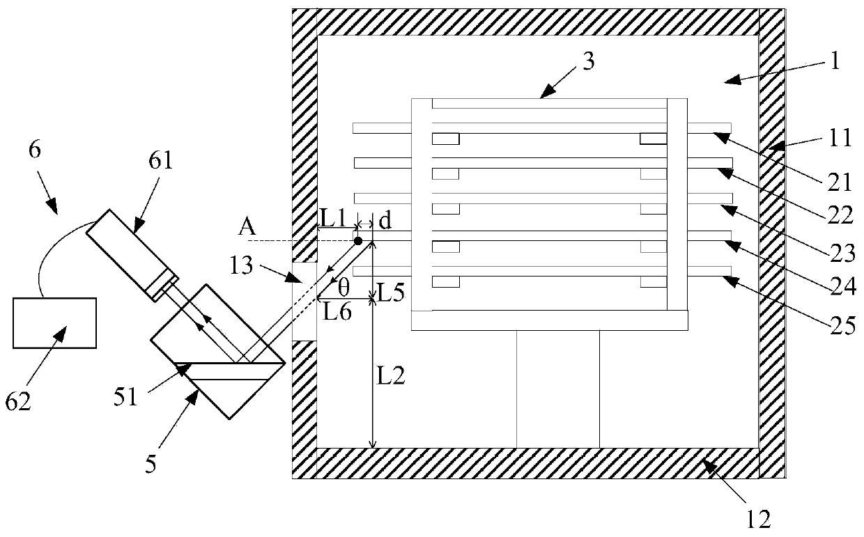
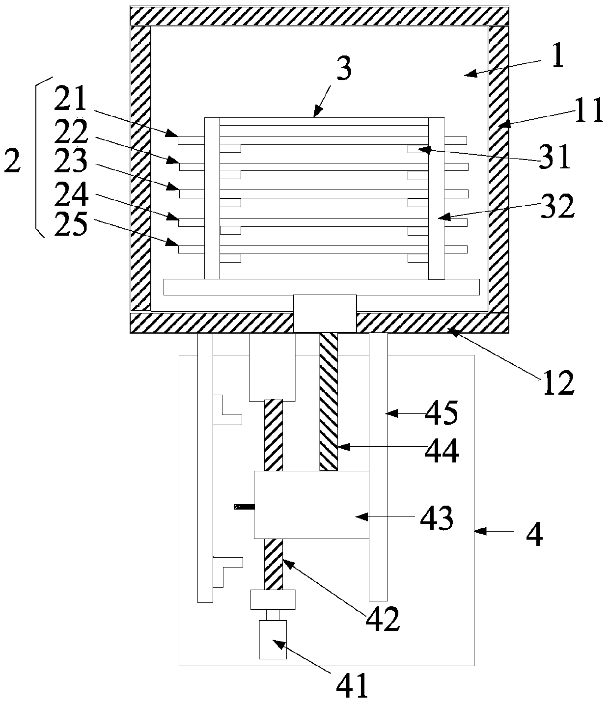
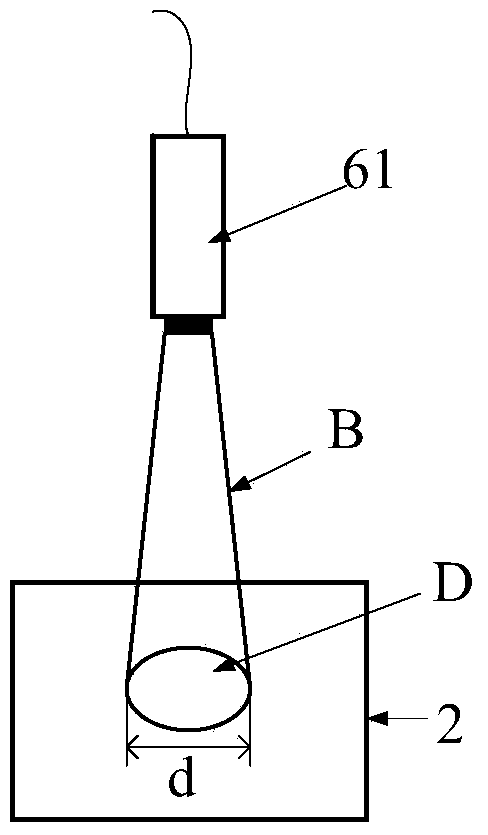
[0030] figure 1 A cross-sectional view of a cooling chamber provided for an embodiment of the present invention. figure 2 It is a schematic structural diagram of the cassette driving device used in the embodiment of the present invention. Please also refer to figure 1 with figure 2 , the cooling chamber 1 includes a carrying device, a perspective window 13 , a reflector 5 and an infrared temperature detector 6 . Wherein, the carrying device is arranged in the cooling chamber 1 for carrying the workpiece to be processed. In this embodiment, the carrying device includes a cassette 3 and a cassette driving device 4 , wherein the cassette 3 is used to carry a plurality of workpieces 2 to be ...


PUM


Abstract

The invention provides a cooling cavity and a semiconductor processing device. The cooling cavity comprises a bearing device, a perspective window, a reflector and an infrared thermoscope; the perspective window is arranged in the wall of the cooling cavity, and infrared light radiated by a processed workpiece irradiates on the reflector via the perspective window; the reflector is arranged in the outer side of the cooling cavity to reflect infrared light irradiate on the reflector to the infrared thermoscope; and the infrared thermoscope receives the infrared light reflected by the reflector, carries out calculation according to the intensity of the infrared light, and thus, obtains the temperature of the processed workpiece. The cooling cavity can prevent the problem of wafer crack or film quality decrease or low production power of equipment due to too high / low cooling speed.

Description

technical field [0001] The invention relates to the technical field of microelectronics, in particular to a cooling chamber and semiconductor processing equipment. Background technique [0002] As a thin film deposition technology, PVD is mainly used for the deposition of various functional thin films. This technology is widely used in pan-semiconductor fields such as integrated circuits, LEDs, and flat panel displays. During the PVD process, it is first necessary to heat the wafer by transferring it to the preheating chamber so that the temperature of the wafer reaches the process temperature, or directly heat the wafer to the process temperature in the reaction chamber, and then heat the wafer in the reaction chamber Complete the thin film sputtering process. When the process is over, the wafer is still in a high temperature state. If it is transferred to the loading and unloading chamber at this time and taken out by the operator directly, there will be the following two...

Claims


Application Information

Patent Timeline
Patent Type & Authority Patents(China)
IPC IPC(8): H01L21/67
CPCH01L21/67011
Inventor 徐宝岗董博宇张军刘绍辉武学伟张鹤南郭冰亮王军
Owner BEIJING NAURA MICROELECTRONICS EQUIP CO LTD
Learn More