Supercharge Your Innovation With Domain-Expert AI Agents!

Remote measuring method and device for antenna azimuth angle and network management system

A technology for antenna azimuth and remote measurement, applied to measuring devices, antennas, measurement angles, etc., can solve problems affecting accuracy, inaccurate antenna azimuth, inaccuracy, etc., and achieve the effect of improving accuracy and reliability

Active Publication Date: 2017-05-24
CHINA TELECOM CORP LTD
View PDF7 Cites 4 Cited by
  • Summary
  • Abstract
  • Description
  • Claims
  • Application Information

AI Technical Summary

Problems solved by technology

[0004] In general, since the antenna cover is directly fixed on the pole, the angle Ф2 between it and the true north direction is generally fixed. However, in practical applications, the antenna cover is likely to change its attitude under the action of external force , such as being blown crookedly in a windy weather, if the attitude of the antenna cover changes, but the angle between the antenna cover and the north direction line recorded in the network management system remains unchanged, the calculated azimuth angle of the antenna will be different. precise
For example, under normal circumstances, the angle between the antenna cover and the north direction line is 5 degrees, if the angle between the reflector of the antenna and the antenna cover is 10 degrees, then the azimuth angle of the antenna is 15 degrees at this time, and if the antenna cover is blown by the wind The angle between the antenna cover and the north direction line becomes 7 degrees, so the azimuth angle of the antenna should be 17 degrees at this time, and because the angle between the antenna cover and the north direction line recorded in the network management system is still 5 degrees, so the network management system The direction angle calculated by the system is still 15 degrees, which is obviously inaccurate and will affect the accuracy of subsequent processing such as network optimization based on the azimuth angle

Method used


Image

  • Remote measuring method and device for antenna azimuth angle and network management system
  • Remote measuring method and device for antenna azimuth angle and network management system
  • Remote measuring method and device for antenna azimuth angle and network management system

Examples


Embodiment Construction

[0035] The present invention will be described more fully hereinafter with reference to the accompanying drawings, in which exemplary embodiments of the invention are illustrated. The following will clearly and completely describe the technical solutions in the embodiments of the present invention with reference to the accompanying drawings in the embodiments of the present invention. Obviously, the described embodiments are only some, not all, embodiments of the present invention. Based on the embodiments of the present invention, all other embodiments obtained by persons of ordinary skill in the art without making creative efforts belong to the protection scope of the present invention. The technical solution of the present invention will be described in various aspects below in conjunction with various figures and embodiments.

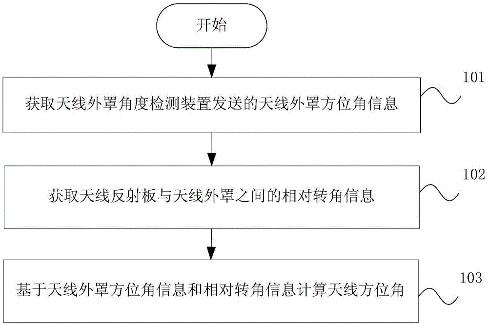
[0036] figure 1 It is a schematic flow chart of an embodiment of the remote measurement method for the antenna azimuth angle according to the pres...


PUM


Abstract

The invention discloses a remote measuring method and device for an antenna azimuth angle and a network management system. The method comprises a step of obtaining antenna radome azimuth angle information sent by an antenna radome angle detection device, a step of obtaining the relative angle information between an antenna reflection plate and an antenna radome, and a step of calculating the antenna azimuth angle based on the antenna radome azimuth angle information and the relative angle information. According to the remote measuring method and device for an antenna azimuth angle and the network management system, the actual azimuth angle of an antenna can be accurately calculated, thus the accuracy of subsequent processing such as network optimization based on the azimuth angle is improved, and the reliability of antenna constructed network optimization is improved.

Description

technical field [0001] The invention relates to the technical field of electronically adjustable antennas, in particular to a remote measurement method, device and network management system for antenna azimuth angles. Background technique [0002] At present, with the advent of the 4G era, the network is becoming denser and denser. One of the challenges operators face is how to improve the efficiency of network maintenance and optimization. The emergence of remote electric adjustable antennas can realize the control of the downtilt angle of the remote antenna within a few minutes, so that fast adjustment, linkage optimization and overall verification are guaranteed. However, since the remote ESC on the existing network can only adjust the electrical downtilt, it cannot adjust the horizontal azimuth. At the same time, LTE networks are becoming denser and denser, and interference coordination and network optimization often require frequent adjustments to azimuth angles. Ther...

Claims


Application Information

Patent Timeline
IPC IPC(8): H01Q3/28H01Q3/34G01C1/00
Inventor 李艳芬朱雪田齐飞孙震强张光辉
Owner CHINA TELECOM CORP LTD
Features
  • R&D
  • Intellectual Property
  • Life Sciences
  • Materials
  • Tech Scout
  • Unparalleled Data Quality
  • Higher Quality Content
  • 60% Fewer Hallucinations
Learn More