
Driving system applied to motion platform

A technology of drive system and dynamic platform, applied in the direction of single motor speed/torque control, electronic commutator, etc., can solve the problem of high cost of drive system and achieve the effect of reducing cost

Inactive Publication Date: 2017-05-24
李淋
View PDF4 Cites 2 Cited by
  • Summary
  • Abstract
  • Description
  • Claims
  • Application Information

AI Technical Summary

Problems solved by technology

[0005] In view of this, the present invention provides a driving system applied to a dynamic platform to solve the problem of high cost of the driving system of a dynamic platform in the prior art

Method used


Image

  • Driving system applied to motion platform
  • Driving system applied to motion platform
  • Driving system applied to motion platform

Examples


Embodiment Construction

[0047] The following will clearly and completely describe the technical solutions in the embodiments of the present invention with reference to the accompanying drawings in the embodiments of the present invention. Obviously, the described embodiments are only some, not all, embodiments of the present invention. Based on the embodiments of the present invention, all other embodiments obtained by persons of ordinary skill in the art without making creative efforts belong to the protection scope of the present invention.

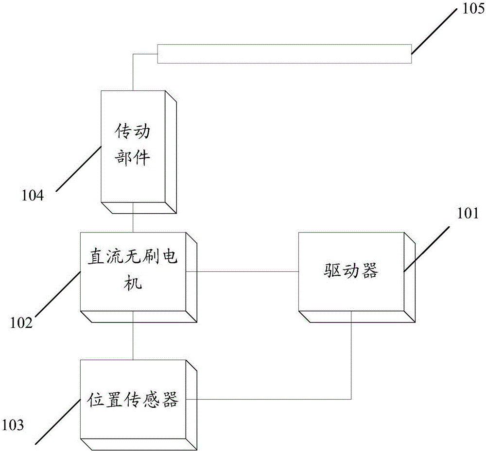
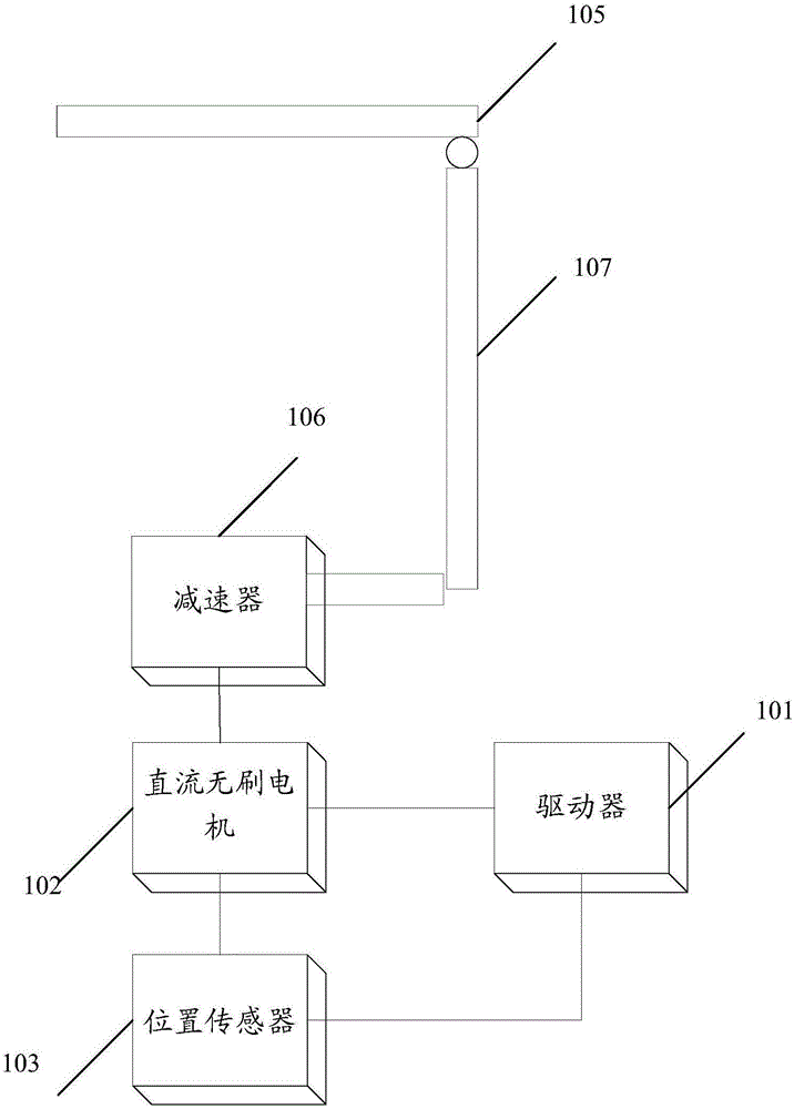
[0048] The embodiment of the present invention provides a driving system applied to a dynamic platform, referring to figure 1 ,include:

[0049] DC brushless motor 102, position sensor 103, driver 101 and transmission part 104; wherein, DC brushless motor 102 is connected with position sensor 103, driver 101 and transmission part 104 respectively; Position sensor 103 is connected with driver 101;

[0050] The position sensor 103 is used to measure the angular...


PUM


Abstract

The application provides a driving system applied to a motion platform. The driving system adopts a brushless direct current (DC) motor; the counter electromotive force produced by the brushless DC motor is a square wave or a sinusoidal wave; the counter electromotive force is basically unchanged within a phase shifting period; the output drive torque fluctuation is smaller. Therefore, accurate measurement does not needed to be continuously carried out on the angular position of a rotor of the motor like the prior art, so that a high-accuracy position sensor is not needed, and a low-accuracy Hall sensor only needs to be used; therefore, the cost of the driving system can be lowered.

Description

technical field [0001] The invention relates to the field of electromechanical control, and more specifically, relates to a driving system applied to a dynamic platform. Background technique [0002] Dynamic platforms, such as dynamic seats, spinning bicycles, etc., can provide users with dynamic experiences such as rising, falling, left and right, front and rear tilt, rotation, etc. synchronously with the visual content, and improve the user's sense of reality. [0003] The drive system of the existing dynamic platform uses a permanent magnet AC servo system, which includes a permanent magnet AC servo motor, a position sensor and a driver. Since the counter electromotive force generated by the permanent magnet AC servo motor is a sine wave, when it is necessary to ensure permanent When the output driving torque of the magnetic AC servo motor is constant, it is necessary to continuously measure the angular position of the rotor of the permanent magnet AC servo motor, so a hi...

Claims


Application Information

Patent Timeline
Patent Type & Authority Applications(China)
IPC IPC(8): H02P6/08H02P6/16
CPCH02P6/08H02P6/16
Inventor 李淋
Owner 李淋
Learn More