Video playing method and device

A technology for video playback and video, applied in CCTV systems, selective content distribution, electrical components, etc., can solve problems such as video playback freezes, and achieve the effect of improving freezes, adapting to a wide range, and achieving simplicity.

Active Publication Date: 2017-05-24
SHENZHEN INFINOVA
View PDF4 Cites 25 Cited by
  • Summary
  • Abstract
  • Description
  • Claims
  • Application Information

AI Technical Summary

Problems solved by technology

[0004] In view of this, the present invention provides a video playback method and device to solve the problem of video freeze during video playback, so that users can obtain a good real-time browsing experience

Method used


Image

  • Video playing method and device
  • Video playing method and device
  • Video playing method and device

Examples


Embodiment 1

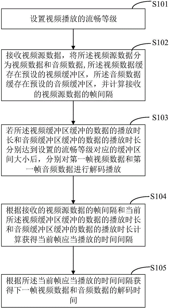
[0031] see figure 1 , figure 1 It is a schematic flow chart of the video playback method provided by Embodiment 1 of the present invention. As shown in the figure, the method may include the following steps:

[0032] Step S101, setting the smoothness level of video playback.

[0033] In the embodiment of the present invention, the fluency of video playback may be affected by network jitter and frame decoding time. Network jitter is due to network bandwidth, signal strength, etc., which will cause the transmitted video source data to fail to reach the receiver at the frame rate when it is sent. If the receiver plays the video at the frame rate when it is received, the video may pause and then resume quickly. broadcast phenomenon. The frame decoding time will affect the fluency level because after receiving the video source data, the received video source data needs to be decoded and rendered before the video, audio or subtitles in the video source data can be played out, and...

Embodiment 2

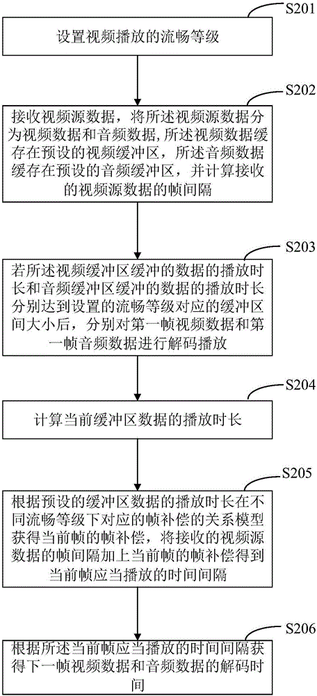
[0053] see figure 2 , figure 2 It is a schematic flow chart of the video playback method provided by Embodiment 2 of the present invention. As shown in the figure, the method may include the following steps:

[0054] Step S201, setting the smoothness level of video playback.

[0055] This step is the same as step S101, for details, please refer to the relevant description of step S101, which will not be repeated here.

[0056] Step S202, receiving video source data, dividing the video source data into video data and audio data, the video data is buffered in a preset video buffer, and the audio data is buffered in a preset audio buffer, and calculating The frame interval of the received video source data.

[0057] This step optimizes the process of calculating the frame interval of the received video source data on the basis of step S102.

[0058] Preferably, calculating the frame interval of the received video source data is specifically:

[0059] When the video source ...

Embodiment 3

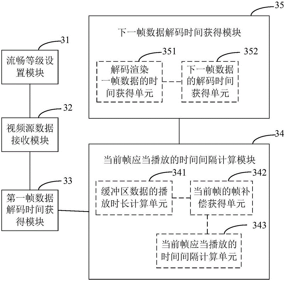
[0114] see image 3 , image 3 It is a schematic block diagram of a video playback device provided in Embodiment 3 of the present invention. For convenience of description, only parts related to the embodiment of the present invention are shown.

[0115] The video playback device can be a software unit, a hardware unit or a combination of software and hardware built into a terminal device (such as a mobile phone, a tablet computer, a notebook, a computer, a wearable device, etc.), or it can be integrated into the terminal as an independent pendant in the device.

[0116] The video playback device includes:

[0117] Smooth level setting module 31, for setting the smooth level of video playback;

[0118] The video source data receiving module 32 is used to receive the video source data, divide the video source data into video data and audio data, cache the video data in a preset video buffer, and cache the audio data in a preset The audio buffer, and calculate the frame inte...


PUM


Abstract

The invention belongs to the technical field of security and protection monitoring and provides a video playing method and device. The video playing method comprises the steps of receiving video source data, dividing the video source data into video data and audio data, buffering the video data in a preset video buffering region and buffering the audio data in a preset audio buffering region and calculating inter-frame space of the received video source data; if the playing duration of the data buffered in the video buffering region and the playing duration of the data buffered in the audio buffering region respectively reach to a size set between the buffering regions, respectively decoding and playing a first frame of the video data and a first frame of the audio data; calculating a time interval of the current frame which shall be played based on the inter-frame space of the received video source data and the playing duration of the data buffered in the current buffering regions; and obtaining the decoding time of the next frame of the video data and the audio data based on the time interval of the current frame which shall be played. The video playing method and device can improve a standstill problem during the video playing process and can improve the video playing smoothness.

Description

technical field [0001] The invention belongs to the technical field of security monitoring, and in particular relates to a video playing method and device. Background technique [0002] The security monitoring system is an independent and complete system that uses optical fiber, coaxial cable or microwave to transmit video signals in a closed loop, from camera to image display and recording. It can reflect the monitored object in real time, vividly and truly. At present, the audio and video data of most security monitoring front-end outlets are stored locally, and real-time audio and video data are transmitted to the monitoring center at the same time. The on-duty personnel can preview or replay in real time in the monitoring center, which greatly reduces the workload of the on-duty personnel and improves the reliability of security defense. [0003] There are two main methods for existing real-time video preview or playback: one is that the receiver immediately arranges t...

Claims


Application Information

Patent Timeline
Patent Type & Authority Applications(China)
IPC IPC(8): H04N7/18H04N21/433H04N21/44
CPCH04N7/18H04N21/4331H04N21/44004
Inventor 欧润林王维治
Owner SHENZHEN INFINOVA
Why Eureka
Try Eureka