Dual-flange prosthetic valve frame

A technology of artificial valves and flanges, applied in heart valves, stents, medical science, etc., can solve problems such as inoperability and inability to withstand surgical procedures

Active Publication Date: 2017-05-24
EDWARDS LIFESCIENCES CORP
View PDF12 Cites 2 Cited by
  • Summary
  • Abstract
  • Description
  • Claims
  • Application Information

AI Technical Summary

Problems solved by technology

Because of these risks, a large number of patients with defective native valves are considered inoperable because their condition is too fragile to withstand the surgical procedure

Method used


Image

  • Dual-flange prosthetic valve frame
  • Dual-flange prosthetic valve frame
  • Dual-flange prosthetic valve frame

Examples


Embodiment Construction

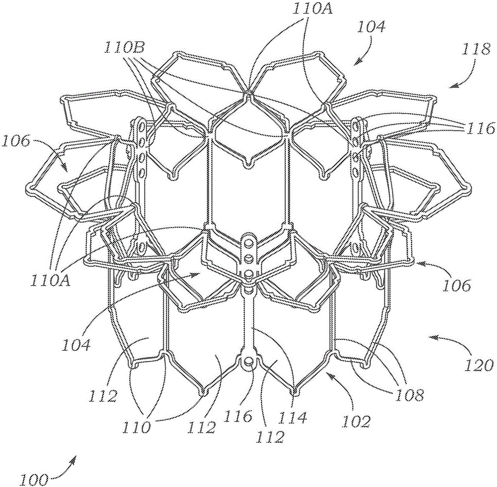
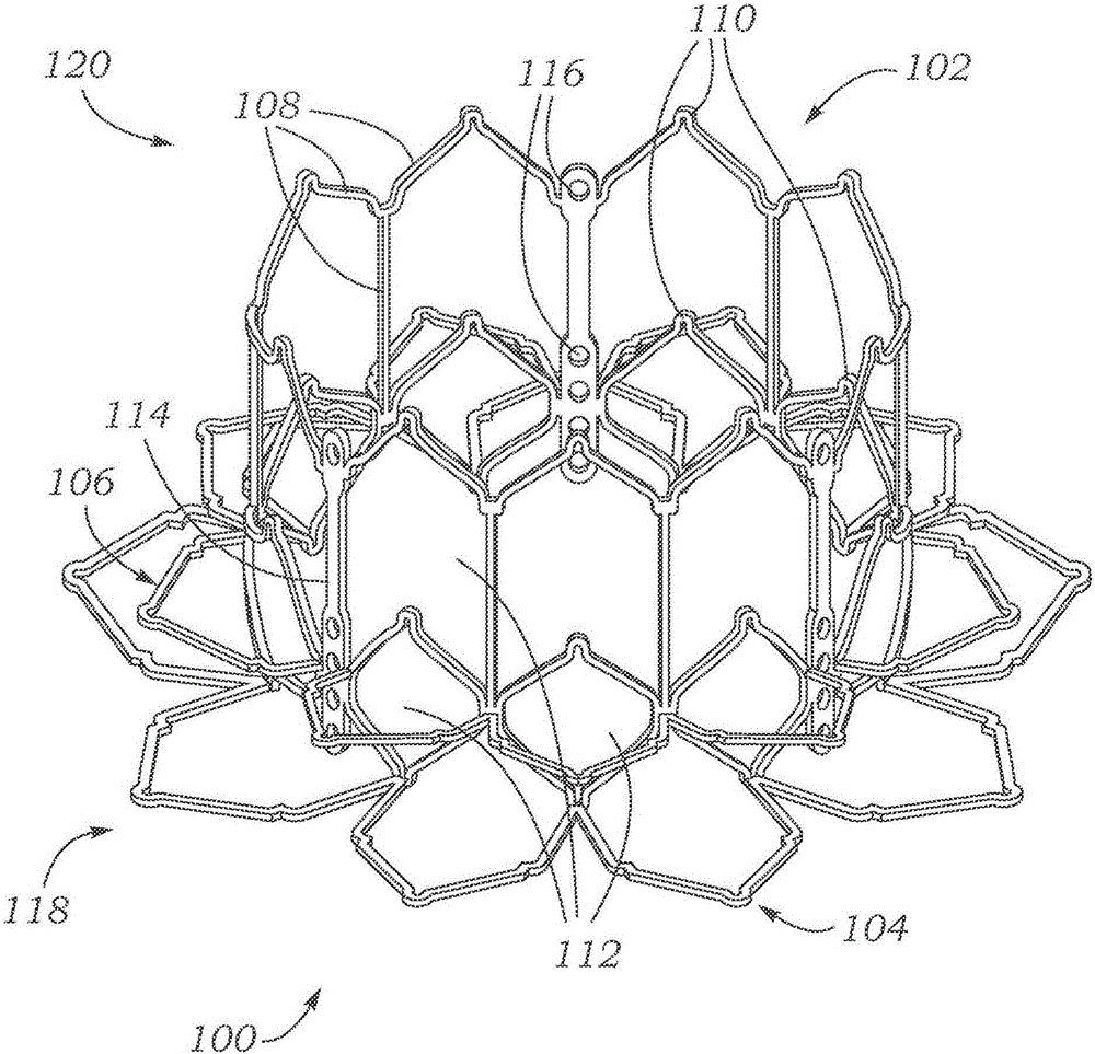
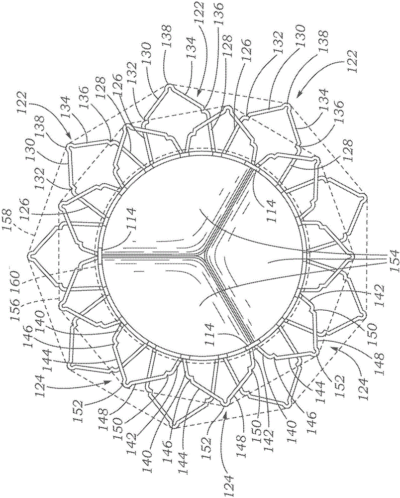
[0033] Frame for use in prosthetic valves

[0034]The framework described herein can be used to provide structure to a prosthetic valve designed to be implanted within a patient's vasculature. The framework described herein can be particularly advantageous for use in prosthetic valves to be implanted within a patient's native mitral valve, but can also be used in prosthetic valves to be implanted in various other parts of a patient's vasculature (e.g. , another natural valve of the heart or various other conduits or orifices in the patient's body). When implanted, the framework described herein can provide structural support for the leaflet structure and / or other components of the prosthetic valve, so that the prosthetic valve can function as a replacement for the natural valve, thereby allowing fluid to pass through the prosthetic valve from the inlet Flow in one direction from outlet port to outlet port, but not in the other or opposite direction from outlet port to inlet...


PUM


Abstract

Embodiments of prosthetic valve frames for implantation within a native mitral valve can include a main body portion, and first and second radially extending flanges coupled to the main body portion. The flanges can be coupled to the main body such that the flanges are spaced father apart from one another when the main body portion is in a crimped configuration than when the main body portion is in an expanded configuration. Associated delivery systems and methods of delivery are provided.

Description

technical field [0001] The present disclosure relates to implantable devices, and more particularly to prosthetic valves for implantation into body vessels such as native heart valve annulus. Background technique [0002] The human heart suffers from a variety of valvular diseases which can lead to significant functional failure of the heart and ultimately require the replacement of natural heart valves with artificial valves. There are many known artificial valves and many known methods of implanting these artificial valves in the human body. [0003] One way of implanting an artificial heart valve in a patient is through open-heart surgery, during which the patient's heart is stopped and the patient is placed on cardiopulmonary bypass (using a so-called "heart-lung machine"). In one common surgical procedure, the diseased native valve leaflets are excised and the artificial valve is sutured to the surrounding tissue at the native valve annulus. Due to the trauma associat...

Claims


Application Information

Patent Timeline
Patent Type & Authority Applications(China)
IPC IPC(8): A61F2/24
CPCA61F2/2412A61F2/2418A61F2002/9665A61F2230/005A61F2230/0052A61F2230/0067A61F2220/0008A61F2230/0069A61F2/2436A61F2/24
Inventor A·H·库珀M·A·彼得森
Owner EDWARDS LIFESCIENCES CORP
Why Eureka
Try Eureka