Printer

A technology for printers and printing media, which is applied in typewriters, printing devices, printing, etc., and can solve problems such as printer function problems, inability to cut backing paper, inability to switch unit movement, etc.

Active Publication Date: 2017-05-24
SATO HLDG CORP
View PDF7 Cites 1 Cited by
  • Summary
  • Abstract
  • Description
  • Claims
  • Application Information

AI Technical Summary

Problems solved by technology

[0007] In the past, in printers capable of switching the issuing mode, when the switching unit (for example, the movable body 11 in Patent Document 1) was configured to be movable between the continuous issuing position and the peeling issuing position, sometimes the The switching unit moves appropriately from the stripped release position to the continuous release position
Failure to properly set the switching unit to the continuous release position can sometimes cause functional problems with the printer
[0008] For example, there may be functional problems such as that the opening and closing cover of the printer cannot be closed, or the backing paper cannot be cut by a cutter even if it can be closed.
In addition, when the switching unit is not properly set to the continuous release position, the presence or absence of the peeling roller cannot be accurately detected by the sensor because the peeling roller of the switching unit is not arranged at an appropriate position.
That is, in the case of adopting a system structure in which the sensor detects whether the peeling roller of the switching unit is at a predetermined position and determines which of the continuous issuing mode or the peeling issuing mode is used, there is a problem as follows: if it cannot be detected Whether the release roller is present or not, the printer's issue mode cannot be accurately determined

Method used


Image

  • Printer
  • Printer
  • Printer

Examples


Embodiment Construction

[0039] The present invention is related to Japanese Patent Application No. 2015-15245 filed with the Japan Patent Office on January 29, 2015, and the contents of this application are incorporated herein by reference.

[0040] Hereinafter, an embodiment of the present invention will be described in detail based on the drawings. In addition, in the drawings for describing the embodiments, in principle, the same reference numerals are attached to the same components, and overlapping descriptions thereof will be omitted.

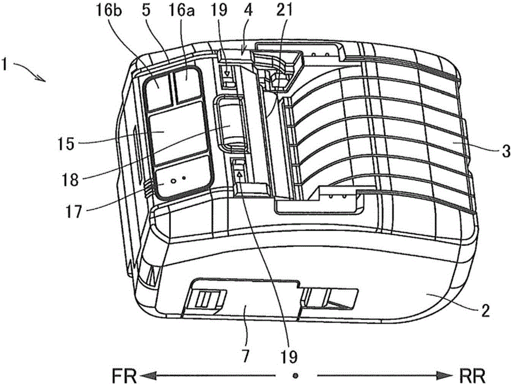
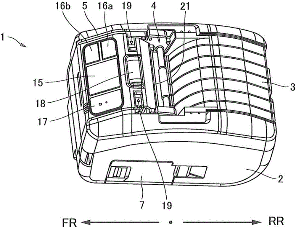
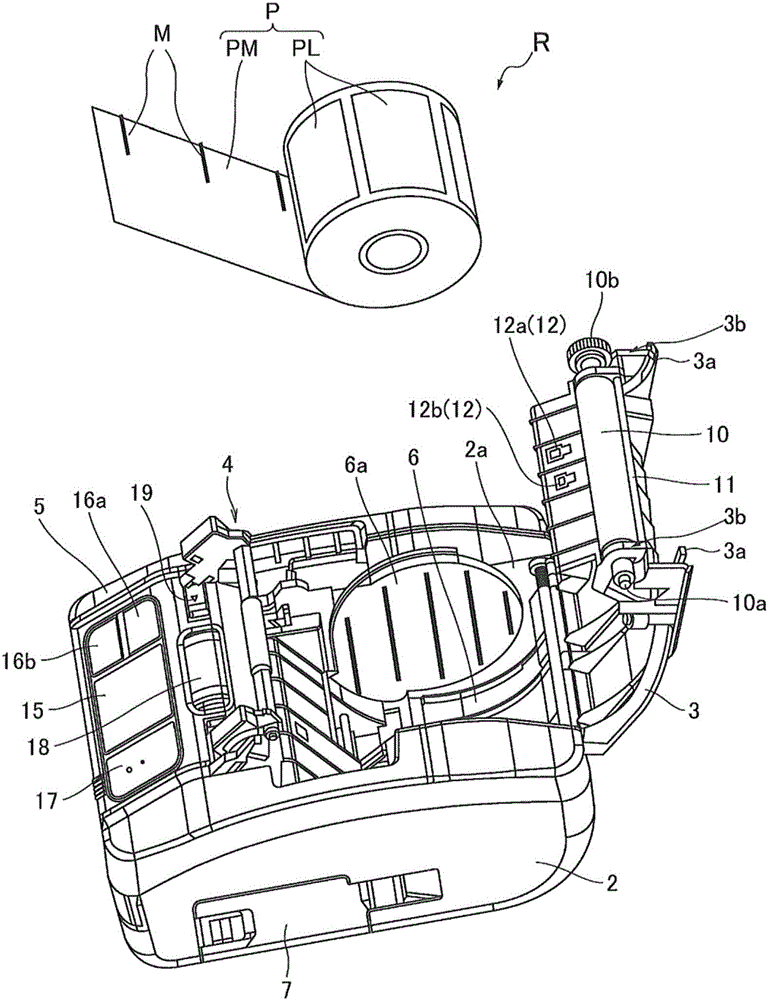
[0041] Figure 1A is an overall perspective view of the printer according to the embodiment in the continuous printing mode, Figure 1B It is an overall perspective view of the printer according to the embodiment in the peeling and issuing mode. figure 2 is to show the open state of the access cover in the Figure 1A and Figure 1B An overall perspective view of the appearance of the printer and roll paper. image 3 yes Figure 1A and Figure 1B A perspective...


PUM


Abstract

This printer is provided with: a holding chamber for holding a roll in which a band-shaped backing sheet is wound in a rolled form; an opening / closing cover for opening and closing the holding chamber; and a switching unit configured so as to be movable between a first position when printing using a first print mode and a second position when printing using a second print mode to switch print modes. A portion of the opening / closing cover comes in contact with the switching unit so that the switching unit is displaced from the first position in the direction of the second position when the opening / closing cover moves from an open state to a closed state.

Description

technical field [0001] The present invention relates to a printer, for example, a printer that prints required information such as characters, symbols, graphics, or barcodes on a label temporarily attached to a backing paper, and has a peeling and issuing function that removes the label from the backing paper and issues it. label printer. Background technique [0002] A label printer is a printer in which the platen roller is rotated with one end of a continuous sheet of paper temporarily pasting a plurality of labels on a tape-shaped backing paper between the thermal head and the platen roller. Print the required information on each label while the continuous paper is being exported and fed in sheet form. [0003] In this label printer, there are two types of distribution methods, continuous distribution and peel-off distribution. The continuous distribution method is a method in which a label serving as a printing medium is temporarily pasted on the backing paper, and th...

Claims


Application Information

Patent Timeline
Patent Type & Authority Applications(China)
IPC IPC(8): B41J29/13B41J3/36B41J15/04B65C9/18
CPCB41J15/042B41J3/4075B41J29/02B41J29/13B65C9/18
Inventor 广濑贤二
Owner SATO HLDG CORP
Why Eureka
Try Eureka