Slag removal mechanism for water tank

A sink and slag knife technology, which is applied to the washing machine/washing machine for tableware, the parts and application of the washing machine/rinsing washing machine for tableware, etc. problems such as poor effect, to avoid clogging and reduce residues

Active Publication Date: 2017-05-31
NINGBO FOTILE KITCHEN WARE CO LTD
View PDF12 Cites 7 Cited by
  • Summary
  • Abstract
  • Description
  • Claims
  • Application Information

AI Technical Summary

Problems solved by technology

[0004] However, in the above-mentioned centrifugal pump, the auxiliary impeller driven by water flow is arranged upstream of the water flow, and the inner diameter of the outer end of the conical tube is larger than the inner diameter of the inner end. Therefore, when the water flow passes through, the rotational speed of the auxiliary impeller is relatively slow, and the cutter cuts the slag. The effect is poor, and the cut aquatic plants directly enter the pump body, and there is still a risk of clogging; in addition, there is only one set of impeller and cutter structure, so that the volume of aquatic plants and other cuts is limited to a small extent

Method used


Image

  • Slag removal mechanism for water tank
  • Slag removal mechanism for water tank
  • Slag removal mechanism for water tank

Examples


Embodiment 1

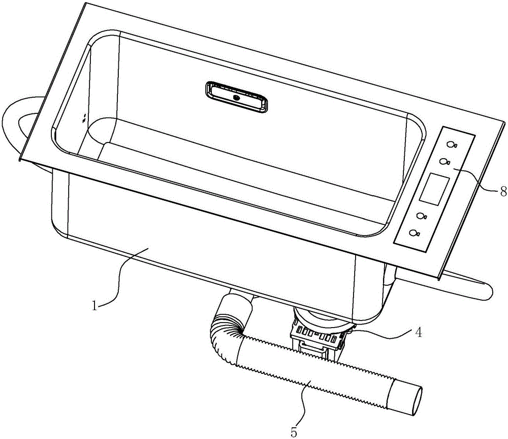
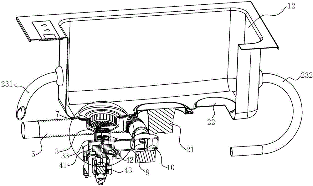
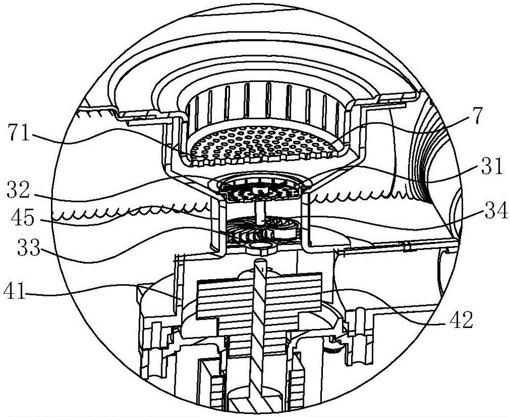
[0025] see figure 1 , figure 2 , a tank cleaning machine, comprising a tank body 1, a cleaning mechanism and a slag discharge mechanism, the slag discharge mechanism comprising a slag twisting mechanism 3, a drainage pump 4, a drain pipe 5, and an upper slag basket 7 arranged at the bottom of the tank body 1, The upper slag basket 7 communicates with the drain pump 4 for filtering the water in the tank body 1 and discharging it. The sink body 1 is provided with a control panel 8 for controlling the cleaning mechanism 2 and the drain pump 4 .

[0026] In this embodiment, the tank body 1 is long and narrow, and the cleaning mechanism includes an ultrasonic generator 21, a heater 22 and a pipeline structure for forming turbulent flow. In order to obtain a better ultrasonic cleaning effect, the ultrasonic generator 21 is arranged on The middle position of the bottom of the water tank body 1 can evenly generate ultrasonic effects on the water tank body 1; Preferable ones may be...

Embodiment 2

[0031] see Figure 5 ~ Figure 8 , in this embodiment, the difference from the first embodiment above is that the slag cutting mechanism 3 also includes a second slag cutting knife 35, a second hydraulic impeller 36 and a second rotating shaft 37, and the second slag cutting knife 35 is located at the first above the slag cutter 32, and the second hydraulic impeller 36 is located below the first hydraulic impeller 33, the second rotating shaft 37 penetrates from the bottom of the first rotating shaft 34 and passes out from the top of the first rotating shaft 34, and the second hydraulic impeller 36 It is arranged at the lower end of the second rotating shaft 37 , and the second slag cutter 35 is arranged at the upper end of the second rotating shaft 37 , so that the second rotating shaft 37 connects the second slag cutter 35 and the second hydraulic impeller 36 . Through the above connection method, the first hydrodynamic impeller 33 and the second hydrodynamic impeller 34 can ...


PUM


Abstract

The invention discloses a slag removal mechanism for a water tank. The slag removal mechanism for the water tank comprises a draining pump and a slag grinding mechanism, the draining pump comprises a pump case, the slag removal mechanism is characterized in that a pump neck is formed on the pump case, the inner diameter of the pump neck is smaller than the upper side and the lower side, and the slag grinding mechanism is arranged in the pump neck. The slag grinding mechanism is arranged in the pump neck of the pump case, a powerful water flow is formed due to the sudden change of the diameter of the pump neck, then a first hydrodynamic impeller is driven to rotate rapidly, a better slag grinding effect is achieved, and the blockage of a pipeline is avoided; two layers of slag baskets are arranged, meshes of the lower layer are much finer to guarantee smooth drainage, the residue slag entering a circulated pipeline structure or a drainage pipe is reduced to further avoid blockage of the pipeline; two sets of slag grinding knifes and a hydrodynamic impeller structure are arranged, so that the two slag grinding knifes form a shearing force to better cut the residue slag into pieces.

Description

technical field [0001] The invention relates to a water tank, in particular to a slag discharge mechanism for the water tank. Background technique [0002] Existing dishwashers, fruit and vegetable cleaning machines, etc., are a device that sprays cold or hot water onto dishes, fruits and vegetables, etc. to remove dirt adhering to dishes, fruits and vegetables, and dishes, fruits and vegetables usually include Pumps and nozzles that spray wash water. Because there are many residues such as vegetable leaves or rice grains on the surface of the dishes, or there are many dirt on the surface of the fruits and vegetables, the sink type washing machine will leave the residues at the bottom of the washing machine after cleaning the dishes, fruits and vegetables, although it can be cleaned through the structure. The adjustment will collect the residue in the slag basket, but the user still needs to manually take out the slag basket for cleaning, which brings a lot of trouble to th...

Claims


Application Information

Patent Timeline
Patent Type & Authority Applications(China)
IPC IPC(8): A47L15/00A47L15/42A47J43/24
CPCA47J43/24A47L15/0086A47L15/4227
Inventor 姚承宏徐慧王吉茅忠群诸永定
Owner NINGBO FOTILE KITCHEN WARE CO LTD
Why Eureka
Try Eureka