Gluing machine system and gluing method

A gluing machine and gluing technology, applied in the direction of injection device, liquid injection device, etc., can solve the problems of cumbersome steps, complex structure of gluing machine, complex and huge structure, etc. Glue service, the effect of simple replacement steps

Inactive Publication Date: 2017-05-31
东方诚建设集团有限公司
View PDF11 Cites 0 Cited by
  • Summary
  • Abstract
  • Description
  • Claims
  • Application Information

AI Technical Summary

Problems solved by technology

However, the structure of the existing gluing machine is very complex and huge, requiring on-site air pumps to supply air. The complex gluing machine system is difficult to transport and install, which has become a long-term technical problem for construction companies.
In particular, the existing glue applicator system needs to disassemble the pressure system after the glue in the plastic bag is used up. After replacing the loading and unloading plastic bag, the pressure system needs to be recalibrated. The steps are cumbersome and time-consuming.
In addition, it is necessary to manually open the plastic bag, and it is difficult to precisely control the position and size of the opening. Once the opening is inaccurate, a large amount of colloid will be wasted
In addition, the pressure source system of the existing gluing machine adopts a hydraulic press or a pneumatic machine, the structure is very complex and huge, and it needs on-site water supply and oil supply support. waste

Method used


Image

  • Gluing machine system and gluing method
  • Gluing machine system and gluing method
  • Gluing machine system and gluing method

Examples


Embodiment Construction

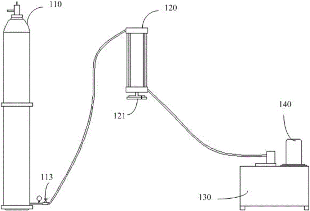
[0052] An embodiment of the present invention provides a glue applicator system, including:

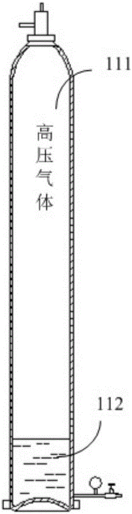
[0053] A pressure vessel containing high-pressure gas and hydraulic oil to provide a stable pressure source for hydraulic cylinders;

[0054] a bracket with slide rails for slidingly mounting the hydraulic cylinder;

[0055] The pressure detection and control device is used to realize the glue application control by measuring the pressure at the inlet and outlet of the metering pump for glue application.

[0056] It can be seen that the embodiment of the present invention achieves a stable pressure source through the pressure vessel containing the high-pressure gas, and the hydraulic cylinder can be easily removed through the bracket with the slide rail, so that the plastic bag can be replaced conveniently. Through the pressure detection and control device, the accurate control of glue output is realized.

[0057] figure 2 It is a schematic diagram of the overall structure of the ...


PUM


Abstract

The invention provides a gluing machine system and a gluing method. A stable pressure source being simple in structure and convenient to convey and install can be provided for on-site gluing operation, a glue bag is convenient to replace, and glue discharge controlling is accurate and clean. The gluing machine system comprises a pressure container which contains high-pressure air and hydraulic oil and is used for supplying a stable pressure source to a hydraulic oil cylinder, a support for slidably installing the hydraulic oil cylinder and with a slide rail and a pressure testing and controlling unit used for measuring the pressure of an inlet and an outlet of a metering pump used for gluing to achieve gluing control.

Description

technical field [0001] The invention relates to the field of building steel structures, in particular to a gluing machine system and a gluing method. Background technique [0002] At present, many factories adopt the form of steel structure. The characteristics of steel structure factory buildings are as follows: 1. Steel structure buildings are light in weight, high in strength and large in span; 2. The construction period of steel structure buildings is short, which reduces investment costs accordingly; 3. Fire resistance of steel structure buildings High, strong corrosion resistance; 4. The steel structure building is easy to move, and the recycling is pollution-free. [0003] figure 1 It is a schematic diagram of a steel structure factory building, such as figure 1 As shown, the top of the factory building is a metal roof panel 11 extending obliquely to the left and right sides with a certain slope, the left and right sides are gables 13, the front is the cornice side ...

Claims


Application Information

Patent Timeline
Patent Type & Authority Applications(China)
IPC IPC(8): B05B9/047B05B12/08B05B15/00
CPCB05B9/047B05B12/085B05B15/00
Inventor 多跃刚陈胜明王越
Owner 东方诚建设集团有限公司
Why Eureka
Try Eureka