Hydraulic flywheel accumulator system based on largest energy accumulation rate, and control method thereof

A technology of accumulators and flywheels, applied in accumulator devices, fluid pressure actuating devices, mechanical equipment, etc., can solve the problems of increasing the number of energy storage elements, unfavorable parts layout, and increasing the quality of hydraulic systems, etc. Achieve high energy storage rate, increase energy density, and reduce volume

Inactive Publication Date: 2015-10-07
JILIN UNIV
View PDF10 Cites 0 Cited by
  • Summary
  • Abstract
  • Description
  • Claims
  • Application Information

AI Technical Summary

Problems solved by technology

Although the energy storage capacity of the energy storage device is improved, the mass and volume of the system are also relatively large, resulting in a large increase in the mass of the hydraulic system, which is not conducive to the layout of parts; the number of energy storage components increases, and the system control is difficult

Method used


Image

  • Hydraulic flywheel accumulator system based on largest energy accumulation rate, and control method thereof
  • Hydraulic flywheel accumulator system based on largest energy accumulation rate, and control method thereof
  • Hydraulic flywheel accumulator system based on largest energy accumulation rate, and control method thereof

Examples


Embodiment Construction

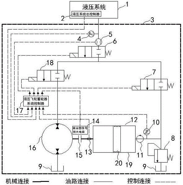
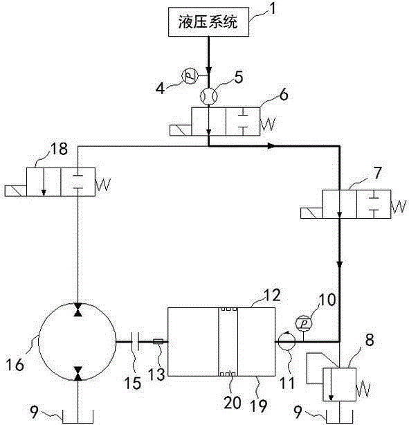
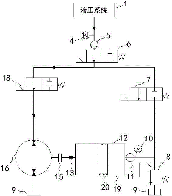
[0026] see figure 1 , is an embodiment of the present invention, which is composed of a hydraulic system 1 and a hydraulic flywheel accumulator system 3 . The hydraulic flywheel accumulator system 3 mainly includes a two-way quantitative pump / motor 16, a clutch 15, a hydraulic flywheel accumulator 12, a high-speed rotary joint 11, a high-speed switching valve, an overflow valve 8, a fuel tank 9, a controller and a sensor; The high-speed on-off valve includes a first high-speed on-off valve 6 , a second high-speed on-off valve 18 and a third high-speed on-off valve 7 , and the sensors include a first pressure sensor 4 , a second pressure sensor 10 , a flow sensor 5 and a speed sensor 13 .

[0027] The shaft end of the bidirectional quantitative pump / motor 16 is connected to one end of the clutch 15 , and the other end of the clutch 15 is connected to the hydraulic flywheel accumulator 12 .

[0028] One end of the high-speed rotary joint 11 is connected to the hydraulic flywhee...


PUM


Abstract

The invention discloses a hydraulic flywheel accumulator system based on largest energy accumulation rate, and a control method thereof. The accumulator system combines functions of a flywheel and a hydraulic accumulator, and a new compound energy storage unit, that is, a hydraulic flywheel accumulator is formed. The hydraulic flywheel accumulator system comprises a hydraulic flywheel accumulator, a two-way constant delivery pump/motor, high-speed switch valves, an overflow valve, a fuel tank, sensors, and a controller. The system is suitable for any system which needs energy storage. Aimed at a plurality of operating modes of the energy storage system, the invention provides a control method which makes energy charging and energy releasing rates optimal. The method comprises selecting a mode which makes energy charging or energy releasing power of a system maximum through controlling on-off of a clutch and operation of the three high-speed switch valves under the conditions of ensuring system rotating speed range and pressure range, so as to realize high-efficient energy charging and energy releasing characteristics of the system, and satisfy instantaneous large power requirement of the system.

Description

technical field [0001] The invention relates to the field of control methods of energy storage systems, in particular to a hydraulic flywheel accumulator system based on the largest energy storage rate and a control method thereof. Background technique [0002] In the hydraulic system, the energy density of the traditional accumulator is low, and it is difficult to meet the energy storage requirements of large-scale systems, and the outlet pressure of the accumulator depends on the energy storage capacity of the accumulator. When the pressure of the accumulator is low, it cannot meet the requirements of the system. Instantaneous high power demand. [0003] The existing machine-hydraulic combined energy storage device (such as the Chinese invention patent application, application publication number: CN 102897012A, publication date: 2013.01.30) is to use the flywheel and the accumulator independently of each other in one system at the same time, which is two kinds of Simple s...

Claims


Application Information

Patent Timeline
Patent Type & Authority Applications(China)
IPC IPC(8): F15B1/04F15B1/027
CPCF15B1/027F15B1/04Y02E60/16
Inventor 汪长虹王继新韩云武张云辉张宇
Owner JILIN UNIV
Why Eureka
Try Eureka