
Efficient equipment for pressing bearing into rear axle

A technology for rear axle and bearing, which is applied in the field of high-efficiency press-in bearing equipment to the rear axle, can solve the problems of low production efficiency, damage to the mounting plate, and hammer injury, so as to improve processing efficiency, improve press-in quality, and reduce labor costs. Effect

Active Publication Date: 2017-05-31
重庆越发机械制造有限公司
View PDF5 Cites 0 Cited by
  • Summary
  • Abstract
  • Description
  • Claims
  • Application Information

AI Technical Summary

Problems solved by technology

[0003] When manually pressing the mounting plate on the operating platform, since the mounting plate will jump relative to the operating platform during the hammering process, it is necessary to press the mounting plate with great force, and if the hammering direction deviates, it is easy to cause accidents or accidents caused by hammering. There is a phenomenon of damage to the mounting plate, so the quality of the rear axle obtained by manually pressing the bearing is not only low, but also the production efficiency is low, and safety accidents are prone to occur

Method used


Image

  • Efficient equipment for pressing bearing into rear axle
  • Efficient equipment for pressing bearing into rear axle
  • Efficient equipment for pressing bearing into rear axle

Examples


Embodiment Construction

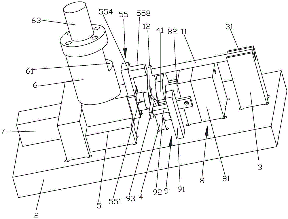
[0049] Such as figure 1 as well as figure 2 As shown, the present embodiment provides a high-efficiency press-in bearing device to the rear axle, including:

[0050] work platform 2;

[0051] The resting seat 3 is arranged on the surface of the working platform 2, and the surface of the resting seat 3 is concave to form a resting groove 31, and the axle body for placing the rear axle in the resting groove 31 is away from the end of the mounting plate;

[0052] The support seat 4 is arranged on the surface of the working platform 2 and is located beside the seat 3. The surface of the support seat 4 is provided with a plate groove (not shown) for placing the mounting plate. When installing, the mounting plate is far away from the shaft body. The edge is placed in the plate groove, and the side of the support seat 4 close to the seat 3 is provided with a pressure bearing plate 41 that supports the mounting plate from the horizontal direction;

[0053] The feeding seat 5 is fi...


PUM


Abstract

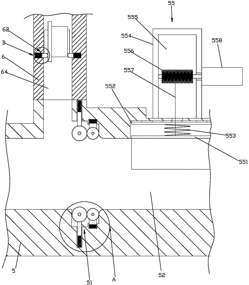
The invention provides efficient equipment for pressing a bearing into a rear axle. The efficient equipment comprises a working platform, a placing seat, a supporting seat, a workpiece supplying seat, a workpiece transmitting barrel and a first air cylinder, wherein the placing seat is arranged on the surface of the working platform, and the surface of the placing seat is sunken inwards to form a placing groove; the supporting seat is arranged on the surface of the working platform and is positioned near the placing seat, and a bearing plate for supporting mounting plate in a horizontal direction is arranged on one side, close to the placing seat, of the supporting seat; the workpiece supplying seat is fixed on the working platform and is positioned on one side, far away from the placing seat, of the supporting seat; a workpiece outlet hole penetrating the workpiece supplying seat is formed in the workpiece supplying seat; the workpiece transmitting barrel is arranged at the top of the workpiece supplying seat, and a workpiece transmitting hole is formed in the workpiece transmitting barrel and is used for vertically placing a plurality of bearings; the workpiece transmitting hole is communicated with the workpiece outlet hole, and the center line of the workpiece transmitting hole is vertical to the center line of the workpiece outlet hole; the first air cylinder is arranged on the side face, far away from the workpiece supplying seat, of the workpiece supplying seat. The efficient equipment has the advantage of realizing the fact that the bearing is automatically pressed into an axle hole of the mounting plate under the premise of ensuring the automatic feeding of the bearing.

Description

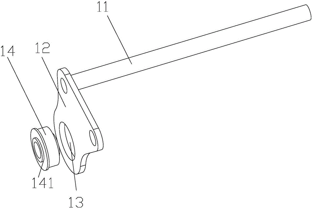
technical field [0001] The invention relates to a device for producing a rear wheel shaft, in particular to a device for pressing a bearing into a rear wheel shaft with high efficiency. Background technique [0002] Such as figure 1 As shown, the rear axle includes a shaft body 11, the shaft body 11 is a cylindrical structure, one end of the shaft body 11 is connected with a mounting plate 12, the plane where the mounting plate 12 is located is perpendicular to the center line of the shaft body 11, and a There is a shaft hole 13, and the shaft hole 13 needs to be pressed into the bearing 14 to form a complete rear wheel shaft. The function of the bearing 14 is to connect the external shaft to play a linkage effect. In the prior art, the mounting plate will be manually pressed on the operating platform, and then the bearing will be hammered into the shaft hole on the mounting plate with force, although the manual operation can achieve a certain degree of pressing the bearing...

Claims


Application Information

Patent Timeline
Patent Type & Authority Applications(China)
IPC IPC(8): B23P19/027
CPCB23P19/027
Inventor 曾勇孙光兵
Owner 重庆越发机械制造有限公司
Learn More