Hydraulic tensioner and tensioning method thereof

A technology of hydraulic stretcher and tie rod, applied in the field of stretcher, can solve the problems of inconvenient oil supply again, bulky pump station, reduced work efficiency, etc., and achieve the effect of preventing excessive force

Inactive Publication Date: 2017-05-31
MAANSHAN SANJIANG MACHINERY
View PDF11 Cites 6 Cited by
  • Summary
  • Abstract
  • Description
  • Claims
  • Application Information

AI Technical Summary

Problems solved by technology

Its shortcoming is that when the stretch reaches the designed stroke, the ejector rod touches the end cover, generating a downward force to push away the steel ball, causing the oil in the cylinder to overflow, and the piston no longer moves upward. The tensioner and the pump station are designed separately. Once the tensioner is overtraveled, when the tensioner is used again, the pump station needs to pressurize and fill the tensioner again through the joint so that the tensioner can play the role of stretching again. , in view of the split design of the pump station and the tensioner, and the bulky size of the pump station, re-supplying brings a lot of inconvenience and reduces work efficiency

Method used


Image

  • Hydraulic tensioner and tensioning method thereof

Examples


Embodiment 1

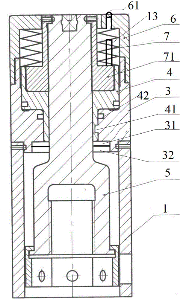
[0058] A hydraulic stretcher in this embodiment includes a base 1, an oil cylinder 3, a piston 4, a pull rod 5 and an end cover 6, the base 1 is located at the lower part of the oil cylinder 3, the pull rod 5 is arranged in the oil cylinder 3, and the diameter of the oil cylinder 3 and the pull rod 5 To be provided with the piston 4 that cooperates with both, the top of the piston 4 is provided with a screw sleeve 71, the end cover 6 is fixed on the upper surface of the oil cylinder 3, and a spring 7 is evenly arranged between the end cover 6 and the screw sleeve 71, and also Including a pumping station 31 and a fuel tank 32, the pumping station 31 and the fuel tank 32 are located at the bottom of the oil cylinder 3, the fuel tank 32 communicates with the oil cylinder 3 through the pumping station 31, and the pumping station 31 is provided with a pressure rod, a high-pressure relief valve and an unloading valve.

Embodiment 2

[0060] A hydraulic extender in this embodiment is similar to Embodiment 1, wherein both the oil tank 32 and the oil cylinder 3 are annular, and the upper part of the ejector rod 5 passes through the annular hole in the middle of the oil tank 32 and the oil cylinder 3, and the oil tank 32 is located in the oil cylinder 3. In the lower part, the oil tank 32 communicates with the oil cylinder 3 through the pump station 31. The pump station 31 is located on the side of the oil tank 32. On the pump station 31, there are pressure rods, pressure gauges, high-pressure relief valves and unloading valves, opposite to the pump station 31. The side of the base 1 is provided with through holes matching the shape of the pressure rod, high pressure relief valve, pressure gauge and unloading valve.

Embodiment 3

[0062] A hydraulic stretcher in this embodiment is similar to Embodiment 1 or 2, wherein it also includes a gear box 14, the gear box 14 is located on the side of the base 1, and the gear box 14 includes a gear one 141, a gear two 142 and Gear 3 143 , gear 1 141 , gear 2 142 and gear 3 143 mesh sequentially. The top of gear 141 is provided with a bolt hole, and gear 3 143 is in contact with the pre-tightening nut in base 1 .


PUM


Abstract

The invention discloses a hydraulic tensioner, and belongs to the field of tensioners. The hydraulic tensioner comprises a pedestal, an oil cylinder, pistons, a pull rod and end covers, wherein the pedestal is located at the lower part of the oil cylinder; the pull rod is arranged in the oil cylinder; the pistons matched with the oil cylinder and the pull rod are arranged in the radial directions of the oil cylinder and the pull rod; screw sleeves are arranged at the tops of the pistons; the end covers are fixed on the upper surface of the oil cylinder; springs are uniformly arranged between the end covers and the screw sleeves; the hydraulic tensioner further comprises a pump station and an oil tank; the pump station and the oil tank are both located at the bottom of the oil cylinder; the oil tank communicates with the oil cylinder through the pump station; a pressing rod, a high pressure overflow valve and an unloading valve are arranged on the pump station; the hydraulic tensioner further comprises a gear box; the gear box is located on the side surface of the pedestal and is in contact with a pre-tightening nut in the pedestal; the hydraulic tensioner further comprises alarm switches and ejector pins; the alarm switches are located in the end covers; the ejector pins are connected with the screw sleeves and are located below the end covers; and the ejector pins and the alarm switches are located on the same straight line. Aiming at the problem that the conventional tensioner is easy to damage due to an overtravel in the prior art, the hydraulic tensioner can realize overtravel reminding, so as to protect the tensioner from being damaged by the overtravel.

Description

technical field [0001] The invention relates to the field of stretchers, in particular to a hydraulic stretcher and a stretching method thereof. Background technique [0002] Bolts and nuts are indispensable parts for assembly in the mechanical field. The fixing method of bolts and nuts is stronger and more reliable than other fixing methods, so it has become the most commonly used method for fixing two or more parts together. Since the bolts used in some large-scale equipment are relatively thick, the pre-tightening force is very large, if the fastening and dismounting of the bolts are done manually, the labor intensity is very high. In addition, because the connection between components requires several, dozens or even dozens of bolts, manual tightening and dismounting of the bolts in sequence will cause uneven stress distribution at each connection position, thereby affecting the strength of the connection. [0003] Hydraulic tensioners have their own travel ranges, if o...

Claims


Application Information

Patent Timeline
Patent Type & Authority Applications(China)
IPC IPC(8): B23P19/06
CPCB23P19/06B23P19/067
Inventor 邰淼鲁志才
Owner MAANSHAN SANJIANG MACHINERY
Why Eureka
Try Eureka