Chemical-mechanical polishing machine and polishing assembly for chemical-mechanical polishing machine

A chemical machinery and polishing machine technology, applied in grinding/polishing equipment, grinding machine tools, grinding devices, etc., can solve the problems of long wafer loading and unloading and transfer time, low working efficiency of chemical polishing machines, etc., to improve work efficiency. Effect

Inactive Publication Date: 2017-05-31
HWATSING TECH +1
View PDF6 Cites 8 Cited by
  • Summary
  • Abstract
  • Description
  • Claims
  • Application Information

AI Technical Summary

Problems solved by technology

When the polishing head is loading and unloading wafers, the polishing disc can only be idle. In addition, it takes a long time to load, unload and transfer the wafers, and the overall work efficiency of the chemical polishing machine is low.

Method used


Image

  • Chemical-mechanical polishing machine and polishing assembly for chemical-mechanical polishing machine
  • Chemical-mechanical polishing machine and polishing assembly for chemical-mechanical polishing machine
  • Chemical-mechanical polishing machine and polishing assembly for chemical-mechanical polishing machine

Examples


Embodiment Construction

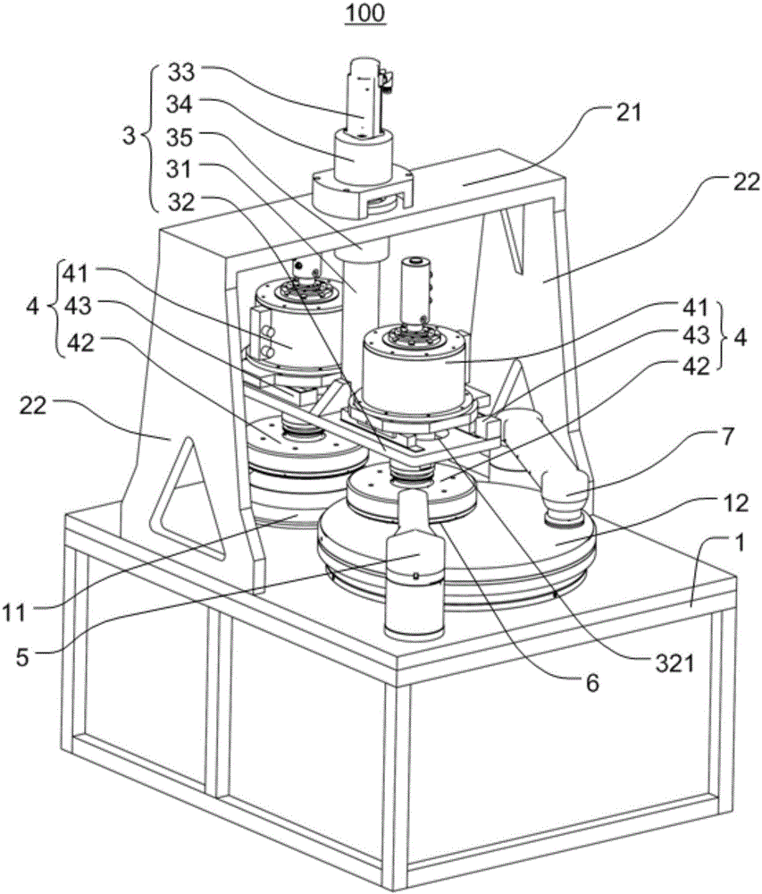
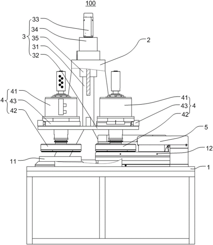
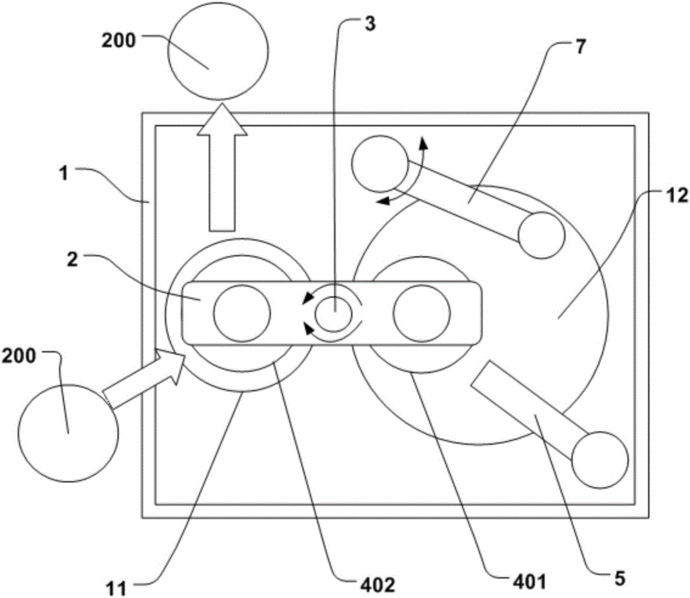
[0033] Embodiments of the invention are described in detail below, examples of which are illustrated in the accompanying drawings. The embodiments described below with reference to the accompanying drawings are exemplary, intended to explain the present invention, but not to be construed as limitations of the present invention, those skilled in the art can change the above-mentioned embodiments within the scope of the present invention , modification, substitution and variation.

[0034] In describing the present invention, it is to be understood that the terms "upper", "lower", "vertical", "horizontal", "inner", "outer", "clockwise", "counterclockwise", "axis The orientations or positional relationships indicated by "to", "radial", "circumferential", etc. are based on the orientations or positional relationships shown in the drawings, which are only for the convenience of describing the present invention and simplifying the description, rather than indicating or implying No ...


PUM


Abstract

The invention discloses a chemical-mechanical polishing machine and a polishing assembly for the chemical-mechanical polishing machine. The polishing assembly comprises a lower support, an upper support, a driving rotating tower and two polishing head assemblies. A worktable and a polishing disc are arranged on the lower support; the upper support is erected on the lower support; the driving rotating tower is suspended on the upper support, and at least one part of the driving rotating tower can rotate in a pivoted mode relative to the lower support; and the two polishing head assemblies are installed on the driving rotating tower and can move between a loading and unloading position corresponding to the worktable position and a polishing position corresponding to the polishing disc position under pivot rotation of the driving rotating tower, wherein when one polishing head assembly is located at the loading and unloading position, the other polishing head assembly is located at the polishing position. According to the polishing assembly for the chemical-mechanical polishing machine, while one polishing head assembly polishes, the other polishing head assembly can load and unload wafers, and the two polishing head assemblies can polish alternately so that continuous working can be conducted, and accordingly working efficiency can be improved.

Description

technical field [0001] The present invention relates to the technical field of planarization processing, and more specifically, to a chemical mechanical polishing machine and a polishing assembly used therefor. Background technique [0002] The chemical mechanical polishing machine in the related art is usually equipped with a polishing head, which switches between the polishing station and the loading station through the translation of the polishing head. When the polishing head is loading and unloading wafers, the polishing disc can only be idle. In addition, it takes a long time to load, unload and transfer the wafers, and the overall working efficiency of the chemical polishing machine is low. Contents of the invention [0003] The present invention aims to solve one of the technical problems in the related art at least to a certain extent. For this reason, the present invention proposes a kind of polishing assembly that is used for chemical mechanical polishing machi...

Claims


Application Information

Patent Timeline
Patent Type & Authority Applications(China)
IPC IPC(8): B24B27/00B24B37/34
CPCB24B37/345B24B27/0076
Inventor 路新春李昆赵德文雒建斌温诗铸许振杰沈攀王同庆郭振宇裴召辉
Owner HWATSING TECH
Why Eureka
Try Eureka