
Lifting type positioning pin device

A positioning pin and lifting technology, which is applied in the direction of manipulators, program-controlled manipulators, manufacturing tools, etc., can solve the problems of complex structure of the lifting pin device, high parts process requirements, and difficult installation, so as to reduce processing technology requirements and installation difficulties , ensuring stability and simplifying the structure

Pending Publication Date: 2017-05-31
YONEGY LOGISTICS AUTOMATION TECH
View PDF8 Cites 5 Cited by
  • Summary
  • Abstract
  • Description
  • Claims
  • Application Information

AI Technical Summary

Problems solved by technology

However, the structure of the lifting pin device is complicated, the installation is difficult, and the requirements for the parts are high, resulting in high cost of the device.

Method used


Image

  • Lifting type positioning pin device
  • Lifting type positioning pin device
  • Lifting type positioning pin device

Examples


Embodiment Construction

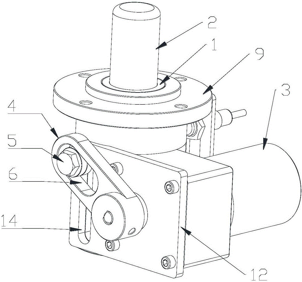
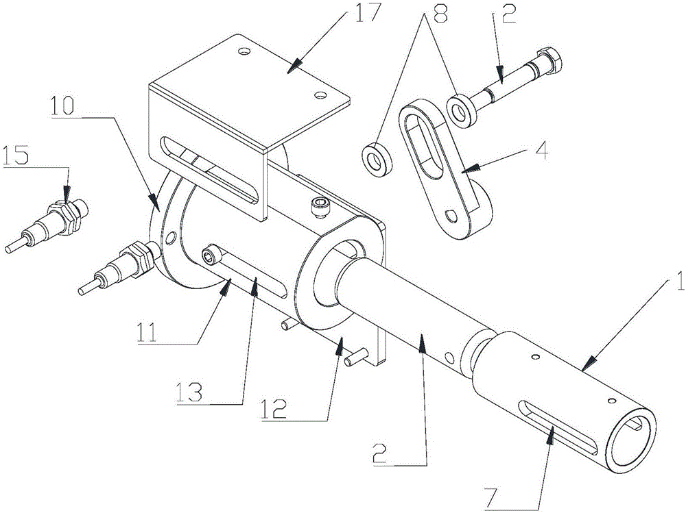
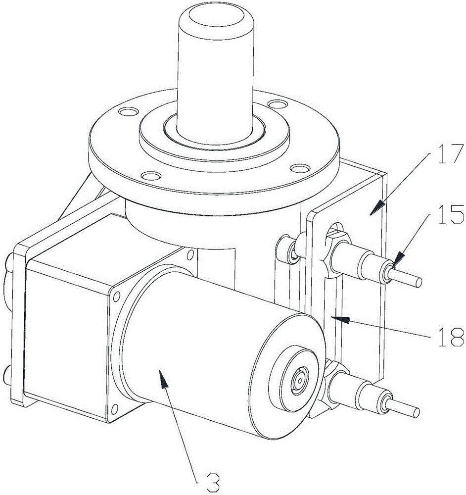
[0022] The specific implementation manners of the present invention will be further described in detail below in conjunction with the accompanying drawings and embodiments. The following examples are used to illustrate the present invention, but are not intended to limit the scope of the present invention.

[0023] Please refer to the attached Figure 1-5 , a lifting positioning pin device provided by the present invention, which includes a guiding body 1, a positioning pin body 2 disposed in the guiding body 1, and a driving mechanism 3 with an output shaft. In this embodiment, the drive mechanism 3 adopts a forward and reverse motor. The driving mechanism 3 is connected to the positioning pin main body 2 through a swing rod 4, and one end of the swing rod 4 is relatively fixedly sleeved on the output shaft of the driving mechanism 3 in the circumferential direction, specifically, the output shaft of the driving mechanism 3 A pin key is provided on the top, and the pin key ...


PUM


Abstract

The invention discloses a lifting type positioning pin device. The lifting type positioning pin device comprises a guiding main body, a positioning pin main body arranged in the guiding main body and a driving mechanism provided with an output rotating shaft. The driving mechanism is connected with the positioning pin main body through a swing rod. One end of the swing rod is relatively fixedly connected on the output rotating shaft of the driving mechanism in a sleeving mode in the circumferential direction. A long-strip-shaped sliding groove is formed in the other end of the swing rod. A connecting rod is inserted in the positioning pin main body. One end of the connecting rod is embedded in the sliding groove of the swing rod in a limited mode. A long-strip-shaped through groove allowing for penetrating of the connecting rod is formed in the guiding main body. The driving mechanism and the positioning pin main body are connected through the swing rod, and the guiding main body with a guiding function is arranged, so that the stability of the lifting movement of the positioning pin main body in the using process is guaranteed effectively; and using of easy-loss fine members such as a reset spring and a gear is avoided, so that the structure of the device is simplified greatly, the machining process requirements and mounting difficulty of parts are reduced, and accordingly the production cost is reduced.

Description

technical field [0001] The invention relates to the technical field of positioning tooling, in particular to a lifting type positioning pin device. Background technique [0002] Unmanned guided vehicle (AGV, Automated Guided Vehicle) refers to a transport vehicle equipped with automatic guidance devices such as electromagnetic or optical, capable of driving along the prescribed guidance path, with safety protection and various transfer functions. AGV is a wheeled vehicle. category of mobile robots. In factories and other sites where materials need to be transferred, the AGV and the rack are connected through the lifting pin device installed on the AGV. In the process of use, on the one hand, the lifting pin device must be able to meet the requirements of AGV's use accuracy and stability; on the other hand, in order to facilitate its popularization and application, it should meet the conditions of easy processing, assembly and installation as much as possible. [0003] The ...

Claims


Application Information

Patent Timeline
IPC IPC(8): B25J9/10
CPCB25J9/108Y02T10/70
Inventor 彭华明朱忠彭清华彭伟
Owner YONEGY LOGISTICS AUTOMATION TECH
Features
  • Generate Ideas
  • Intellectual Property
  • Life Sciences
  • Materials
  • Tech Scout
  • Unparalleled Data Quality
  • Higher Quality Content
  • 60% Fewer Hallucinations
Learn More