Balance structure applied to automobile
A technology for balancing structures and automobiles, which is applied to vehicle components, elastic suspensions, interconnection systems, etc., and can solve problems such as vehicle rollover, vehicle body shaking or tail flicking, and lateral deviation of the center of gravity to achieve good controllability, Conducive to the effect of driving safety
- Summary
- Abstract
- Description
- Claims
- Application Information
AI Technical Summary
Problems solved by technology
Method used
Image
Examples
Embodiment 1
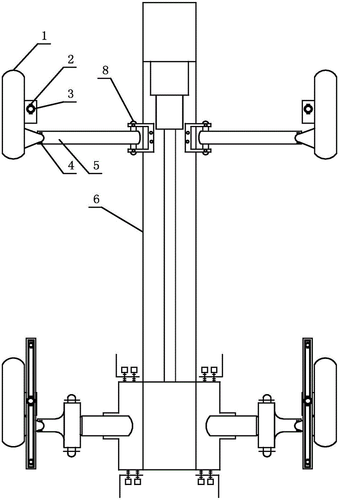
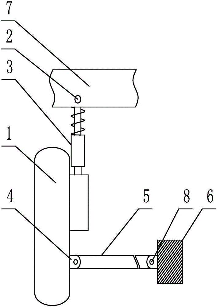
[0036] Such as Figure 1 to Figure 3 Shown, a kind of balance structure that is applied to automobile, a kind of balance structure that is applied to automobile, comprises wheel support 1, vehicle axle 5, shock absorber 3, auxiliary frame 6 and vehicle frame 7, and described vehicle axle 5 is used for For connecting the wheel support 1 and the sub-frame 6, the shock absorber 3 is used to connect the wheel support 1 and the vehicle frame 7, and also includes a first hinge part 2, a second hinge part 4 and a third hinge part 8, the The axle 5 is hingedly connected to the wheel support 1 through the second hinge part 4, the axle 5 is hingedly connected to the subframe 6 through the third hinge part 8, and the shock absorber 3 is connected to the frame through the first hinge part 2. 7 hinged connection;
[0037] The shock absorber 3 can be rotated at the first hinge part 2 as a rotation point, and the axis direction of the rotation is parallel to the length direction of the sub-...
Embodiment 2
[0043] Such as Figure 1 to Figure 3 As shown, this embodiment is further limited on the basis of Embodiment 1: as a technical solution with simple structure and easy implementation, the first hinged part 2, the second hinged part 4 and the third hinged part 8 are three Both are hingedly connected by the hinge shaft 11 , and the axis direction of the hinge shaft 11 is located in the length direction of the sub-frame 6 .
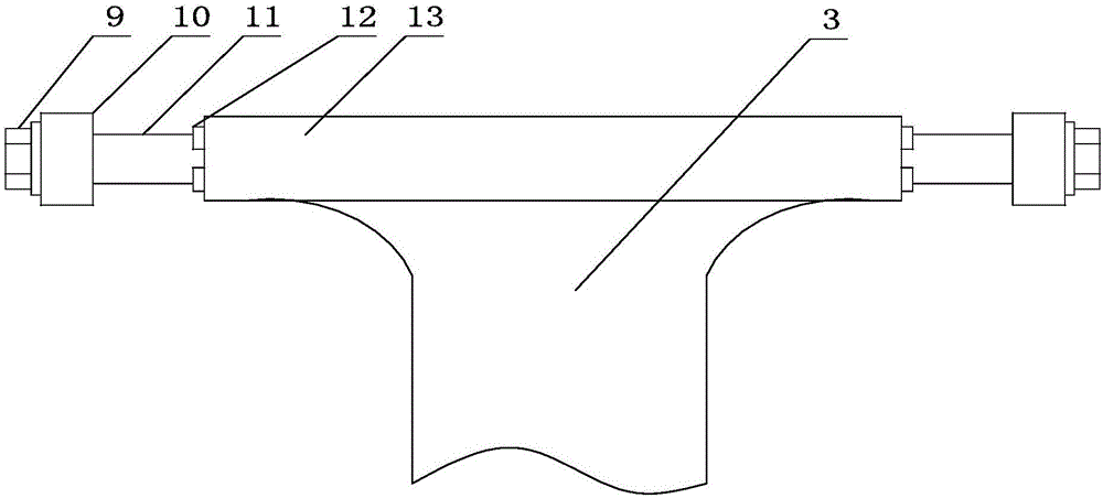
[0044] As a specific realization of the first hinged part 2, the second hinged part 4 and the third hinged part 8, the first hinged part 2, the second hinged part 4 and the third hinged part 8 all include hinged joints. Shaft 11, two bearings 10 mounted on different ends of the hinged shaft 11, and a bushing 13 sleeved on the hinged shaft 11 and located between the two bearings 10;
[0045] The sub-frame 6 , the wheel support 1 and the vehicle frame 7 are all provided with 10 bearings for installing the bearing 10 , and the upper end of the shock absorber 3 ...
Embodiment 3
[0053] This embodiment is further defined on the basis of the technical solution provided in embodiment 1: the shock absorber 3 is fixedly connected to the wheel support 1, and the first hinge part 2 is a ball joint. This scheme can cancel the hinge point between the lower end of the shock absorber 3 and the wheel support 1, so that the car body provided by this scheme has a smaller failure rate during use.
PUM
 Abstract
Description
Claims
Application Information
 - R&D
- Intellectual Property
- Life Sciences
- Materials
- Tech Scout
- Unparalleled Data Quality
- Higher Quality Content
- 60% Fewer Hallucinations
Browse by: Latest US Patents, China's latest patents, Technical Efficacy Thesaurus, Application Domain, Technology Topic, Popular Technical Reports.
© 2025 PatSnap. All rights reserved.Legal|Privacy policy|Modern Slavery Act Transparency Statement|Sitemap|About US| Contact US: help@patsnap.com


