A circular dry wheel-rail lubrication system

A lubricating system, circular technology, applied in the directions of rail lubrication, rail wetting/lubrication, railway car body parts, etc., can solve the problem that the spray cannot be accurately sprayed to the designated position, the braking and driving performance are affected, and the liquid lubrication is easy to form oil pollution. and other problems, to achieve the effect of being conducive to environmental protection, no fire hazard, and low friction coefficient

Active Publication Date: 2019-02-19
GUAGNZHOU WINLANE RUBBER & PLASTIC COMPONENTS
View PDF5 Cites 0 Cited by
  • Summary
  • Abstract
  • Description
  • Claims
  • Application Information

AI Technical Summary

Problems solved by technology

[0006] 1. Affected by curves and wind, the grease sprayer cannot accurately spray to the designated position, which affects the lubrication effect;
[0007] 2. Liquid lubricating oil will migrate, and the long-term performance is poor;
[0008] 3. Liquid lubricating oil will absorb dust and affect the lubrication effect;
[0009] 4. Liquid lubricating oil may migrate to the wheel-rail tread, affecting braking and driving performance;
[0010] 5. Liquid lubricating oil is flammable, and it is easy to burn when encountering sparks;
[0011] 6. Liquid lubrication is easy to form oil pollution, which is not conducive to environmental protection;
[0012] 7. Complex structure, troublesome installation and maintenance;
[0014] 9. High cost

Method used


Image

  • A circular dry wheel-rail lubrication system
  • A circular dry wheel-rail lubrication system
  • A circular dry wheel-rail lubrication system

Examples


Embodiment Construction

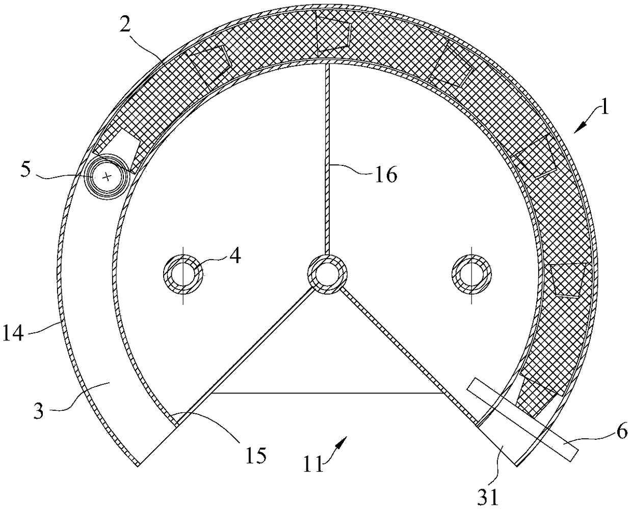
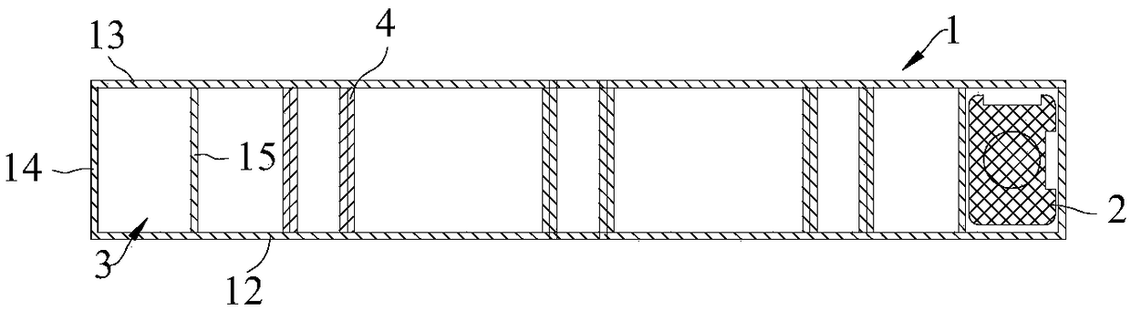
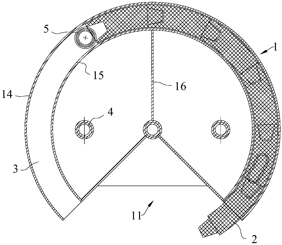
[0048] refer to Figure 1 to Figure 11 , which shows the specific structure of the preferred embodiment of the present invention. The structural characteristics of each element of the present invention will be described in detail below, and if there is a description of the direction (up, down, left, right, front and back), it is based on figure 1 The shown structure is a reference description, but the actual use direction of the present invention is not limited thereto.

[0049] The present invention provides a circular dry wheel-rail lubrication system, including a lubricating block 2 and a circular box 1, see figure 1 , image 3 , the lubricating block 2 is bent to one side along the central arc to form an arc shape 20, and a notch 11 is provided on the box body, and the notch 11 is fan-shaped. The box body 1 is provided with an annular guide groove 3 for placing the lubricating block 2, and the annular guide groove 3 forms a lubricating block outlet 31 at the gap 11, and...


PUM


Abstract

The invention discloses a circular dry lubrication system for wheels and rails, and is applied to the field of lubrication technologies for locomotive wheel sets and rails. The circular dry lubrication system comprises lubrication blocks and a circular box. Each lubrication block is bent towards a side along a center arc to form an arc, a notch is arranged on the box, an annular guide groove for arranging the lubrication blocks is formed in the box and is provided with a lubrication block outlet which is formed in the notch, and a feeding mechanism is arranged in the box and can provide acting force for pushing the lubrication blocks arranged in the annular guide groove out of the lubrication block outlet one by one. The circular dry lubrication system has the advantages that the box can be fixedly mounted on wheel carriers of trains when the circular dry lubrication system is used, the notch of the box directly faces the edges of the wheels of the trains, the lubrication blocks in the box can slide along the annular guide groove under the effect of the feeding mechanism and can be in contact with specified locations of rims of the trains, and constant pressures can be generated; the wheels rotate when the trains run, tangential friction is carried out between the wheels and the lubrication blocks, an extremely thin lubrication film can uniformly cover each rim under friction effects of the corresponding lubrication blocks and the rim, accordingly, wheel-rail friction coefficients can be lowered to a great extent, and abrasion of the wheels and the rails can be reduced.

Description

technical field [0001] The invention is used in the technical field of locomotive wheelset and track lubrication, and in particular relates to a circular dry wheel-rail lubrication system. Background technique [0002] With the large number of internal combustion and electric locomotives on the road and the development of railways in the direction of speed increase and heavy load, the side wear of curved rails on busy railway lines in my country is on the rise, and the problem of wheel and rail wear is becoming more and more prominent; [0003] When the rolling stock is running on a curve, there are often two points of contact between the guide wheels. In addition to the tread contact, the outer wheel rim and the gauge line of the outer rail are close to each other. The guide wheels hit the rail at this point, and the rail is also formed at this point. At the same time, the running direction of the wheel pair on the wheel-rail contact point and the tangential direction of th...

Claims


Application Information

Patent Timeline
Patent Type & Authority Patents(China)
IPC IPC(8): B61K3/02
CPCB61K3/02
Inventor 伍华东韦勇坚黄海明张春龙张绍彬潘金定张富强
Owner GUAGNZHOU WINLANE RUBBER & PLASTIC COMPONENTS
Why Eureka
Try Eureka