
Buffering holder

A technology of gimbal and fixed platform, applied in the field of aerial photography gimbal, can solve problems such as unfavorable image quality clarity, shock-absorbing ball shaking, etc., and achieve the effect of good image quality, stable sliding, and even sliding.

Inactive Publication Date: 2017-05-31
天津天信通达科技有限公司
View PDF0 Cites 10 Cited by
  • Summary
  • Abstract
  • Description
  • Claims
  • Application Information

AI Technical Summary

Problems solved by technology

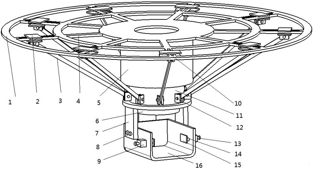
[0002] With the development of society and the advancement of science and technology, people's needs are also increasing. Aerial photography has high application value in many fields. Aerial photography is used to collect pictures, measure land, etc., so the quality of the pictures taken by it The requirements are relatively high, and the existing aerial photography devices are far from meeting such requirements. When encountering collisions or space restrictions due to external interference, it is inevitable that the collision will cause the image quality to be unclear. Some aerial photography equipment is designed to reduce vibration. To affect the image quality, shock-absorbing balls are usually installed on the gimbal. Although the shock-absorbing balls can play the role of anti-vibration, the shock-absorbing balls themselves are elastic. Under such circumstances, it is easy to cause the shaking of the shock-absorbing ball itself, which is not conducive to the clarity of the image quality. In view of this situation, the present invention provides a buffer-type pan-tilt, which achieves the shock-absorbing effect of the pan-tilt through a simple mechanical structure, and can Achieve horizontal and vertical buffering and shock absorption to achieve high-quality aerial photography, better image quality, less damage to the machine itself, and better stability

Method used


Image

  • Buffering holder

Examples


Embodiment Construction

[0024] It should be noted that, in the case of no conflict, the embodiments of the present invention and the features in the embodiments can be combined with each other.

[0025] In describing the present invention, it should be understood that the terms "center", "longitudinal", "transverse", "upper", "lower", "front", "rear", "left", "right", " The orientations or positional relationships indicated by "vertical", "horizontal", "top", "bottom", "inner" and "outer" are based on the orientations or positional relationships shown in the drawings, and are only for the convenience of describing the present invention and Simplified descriptions, rather than indicating or implying that the device or element referred to must have a particular orientation, be constructed and operate in a particular orientation, and thus should not be construed as limiting the invention. In addition, the terms "first", "second", etc. are used for descriptive purposes only, and should not be understood ...


PUM


Abstract

The invention provides a buffering holder. The buffering holder comprises a fixed platform and a fixing rod which is placed under the fixed platform and coaxially and fixedly connected with the fixed platform; an elastic element is arranged to penetrate through the fixing rod; a supporting block is also connected to the fixing rod in a sliding manner; the fixed platform consists of a plurality of circular rings; the circular rings are connected with each other through a plurality of supporting rods; slide blocks are connected to the supporting rods in a sliding manner; sliding rods are hinged at the bottoms of the the slide blocks; one end, far away from the fixed platform, of the supporting block extends downwards to be provided with a plurality of brackets; placing platforms are connected to the brackets; and same locking mechanisms are symmetrically arranged on two sides of the placing platforms. According to the buffering holder, the damping function of the holder is achieved by using a simple mechanical structure, buffering and damping in a horizontal direction and a vertical direction can be achieved to realize high quality aerial photography, good image quality is realized, damage to a camera is reduced and stability is good.

Description

technical field [0001] The invention belongs to the field of cloud platforms for aerial photography, in particular to a cushioning platform. Background technique [0002] With the development of society and the advancement of science and technology, people's needs are also increasing. Aerial photography has high application value in many fields. Aerial photography is used to collect pictures, measure land, etc., so the quality of the pictures taken by it The requirements are relatively high, and the existing aerial photography devices are far from meeting such requirements. When encountering collisions or space restrictions due to external interference, it is inevitable that the collision will cause the image quality to be unclear. Some aerial photography equipment is designed to reduce vibration. To affect the image quality, shock-absorbing balls are usually installed on the gimbal. Although the shock-absorbing balls can play the role of anti-vibration, the shock-absorbing ...

Claims


Application Information

Patent Timeline
IPC IPC(8): B64D47/08F16F15/08
CPCB64D47/08F16F15/08
Inventor 葛辰
Owner 天津天信通达科技有限公司
Learn More