Tray unstacking/stacking machine

A pallet and stacker technology, applied in the direction of unstacking of objects, conveyors, stacking of objects, etc., can solve the problems of inconvenient maintenance, large structure, complex transmission, etc., achieve simple structure, simple and compact structure, save transmission The effect of the piece

Pending Publication Date: 2017-05-31
江苏保力自动化科技有限公司
View PDF0 Cites 0 Cited by
  • Summary
  • Abstract
  • Description
  • Claims
  • Application Information

AI Technical Summary

Problems solved by technology

[0003] The technical problem to be solved by the present invention is: most of the existing pallet depalletizing and stacking machines mentioned in the background technolo

Method used


Image

  • Tray unstacking/stacking machine
  • Tray unstacking/stacking machine
  • Tray unstacking/stacking machine

Examples


Embodiment

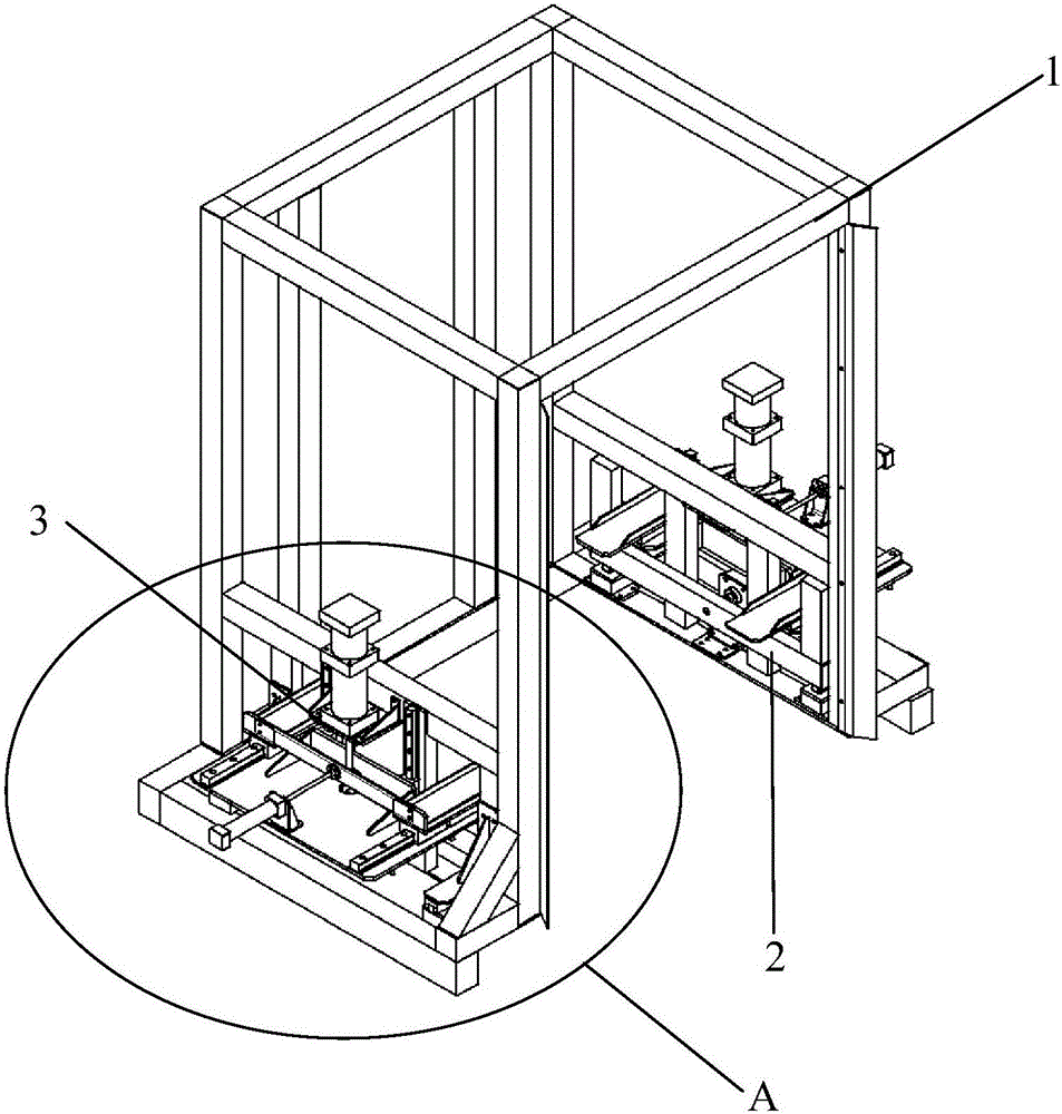
[0023] Such as figure 1 with 2 Shown, be the pallet destacking stacker of the present embodiment;

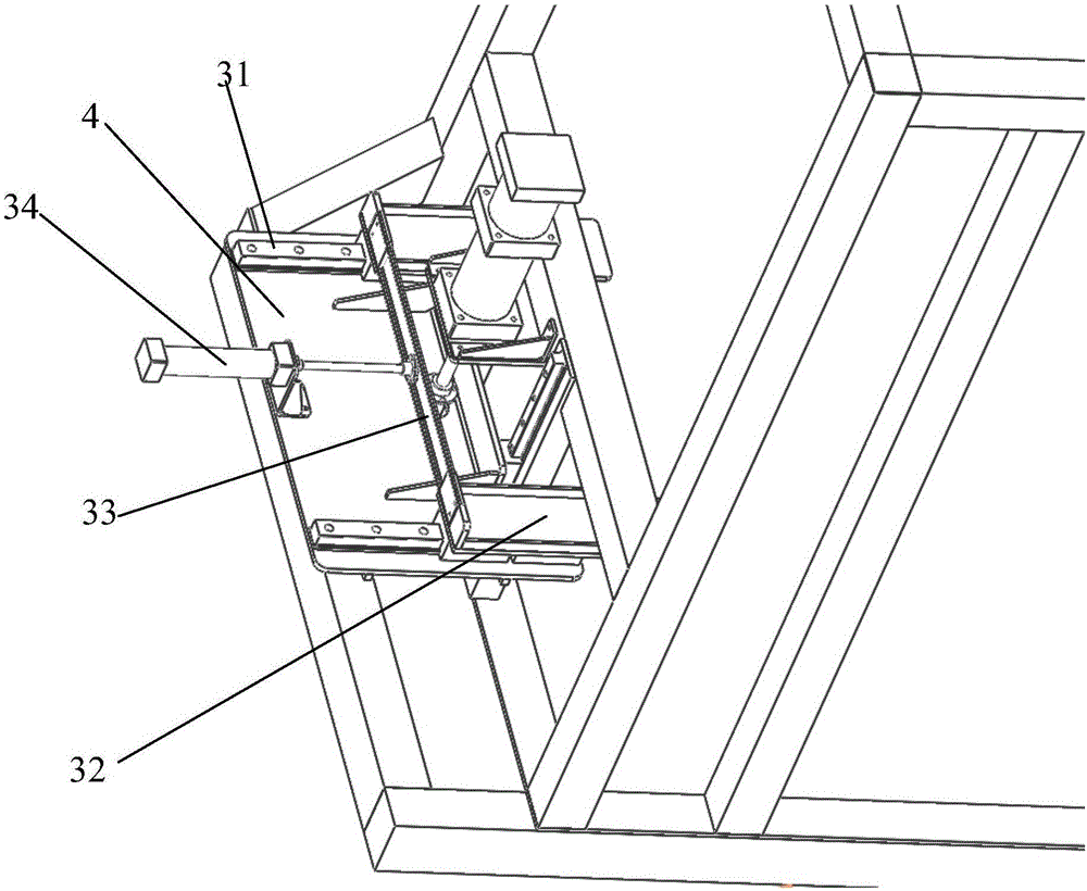
[0024] A pallet depalletizing and palletizing machine, comprising a "door"-shaped rigid support 1, two pneumatic clapping mechanisms 2 and two pallet fork mechanisms 3; figure 1 with 2 As shown, the rigid support 1 in the shape of a "door" is placed on the ground, and the interior of the rigid support is a fixed-point space for the pallet; There is a pneumatic slapping mechanism 2 for sorting the trays, and the two pneumatic slapping mechanisms 2 are symmetrically arranged; above the two pneumatic slapping mechanisms, a hanging plate 4 is provided to hold the tray and can drive the tray to slide vertically up and down The pallet fork mechanism3.

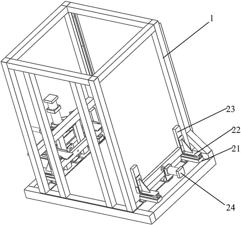
[0025] Such as figure 2 As shown, the bottom of the left side of the rigid support 1 and the bottom of the rear side protrude outward and are respectively provided with an open steel beam 11 for installing a pneumatic clapping me...


PUM


Abstract

The invention discloses a tray unstacking/stacking machine which is aimed at solving the technical problems that the existing tray unstacking/stacking machine mentioned in the background art mostly adopts a mechanical transmission structure and a motor for driving and is characterized by huge structure, complicated transmission and inconvenience in maintenance. The technical scheme is as follows: the tray unstacking/stacking machine comprises an n-shaped rigid bracket placed on the ground, wherein tray entrance and exit are formed at the front and back of the rigid bracket; pneumatic beating and finishing mechanisms are arranged on the left side surface and right side surface of the rigid bracket respectively; the two pneumatic beating and finishing mechanisms are symmetrically arranged; tray fork mechanisms are arranged above the two pneumatic beating and finishing mechanisms; and a hanging plate is glidingly arranged on the rigid bracket and is vertical to the side surface of the rigid bracket. The tray unstacking/stacking machine disclosed by the invention has the following advantages: with an air cylinder serving as a motion execution component and by replacing the transmission way and adopting a pneumatic component to execute motion, the structure is simple, compact and not complicated and neater than that of traditional machinery.

Description

technical field [0001] The invention relates to a pallet depalletizing and palletizing machine. Background technique [0002] Most of the existing pallet depalletizing and palletizing machines of the prior art use a mechanical transmission structure and are driven by a motor, which is characterized by huge structure, complicated transmission and inconvenient maintenance. Contents of the invention [0003] The technical problem to be solved by the present invention is: most of the existing pallet depalletizing and stacking machines mentioned in the background technology only use mechanical transmission structures and are driven by motors, which are characterized by huge structures, complicated transmissions and inconvenient maintenance. [0004] The design idea of ​​the present invention is to propose a pallet depalletizing and palletizing machine based on the cylinder as the motion executing part and having dual functions of pallet depalletizing and palletizing. [0005] ...

Claims


Application Information

Patent Timeline
IPC IPC(8): B65G57/03B65G59/02
CPCB65G57/03B65G59/02B65G2201/0258
Inventor 陆锦林
Owner 江苏保力自动化科技有限公司
Why Eureka
Try Eureka