Uncoiling and discharging machine for coiled plates

A technology of feeding machine and coiling plate, applied in the field of coiling plate unwinding equipment, can solve the problems of inconvenient use, difficult to adapt to different specifications of coiled plate materials, unable to adapt to various specifications of coiled plate materials, etc., to achieve simple structure, Use flexible effects

Inactive Publication Date: 2017-05-31
安陆市华誉金属网机制造有限公司
View PDF7 Cites 1 Cited by
  • Summary
  • Abstract
  • Description
  • Claims
  • Application Information

AI Technical Summary

Problems solved by technology

[0002] Most of the existing coiling and unwinding equipment fix various specifications of coiling materials on various mandrels in various forms, and then uncoil and unwind the coiled materials. Often a mandrel It is also difficult to adapt to coiling materials of different specifications, and the distance between the mandrels is fixed, which cannot adapt to coiling materials of various specifications. At the same time, it cannot be adjusted to realize active or passive unwinding operations according to actual use requirements. Therefore, Its use has many inconveniences

Method used


Image

  • Uncoiling and discharging machine for coiled plates
  • Uncoiling and discharging machine for coiled plates
  • Uncoiling and discharging machine for coiled plates

Examples


Embodiment

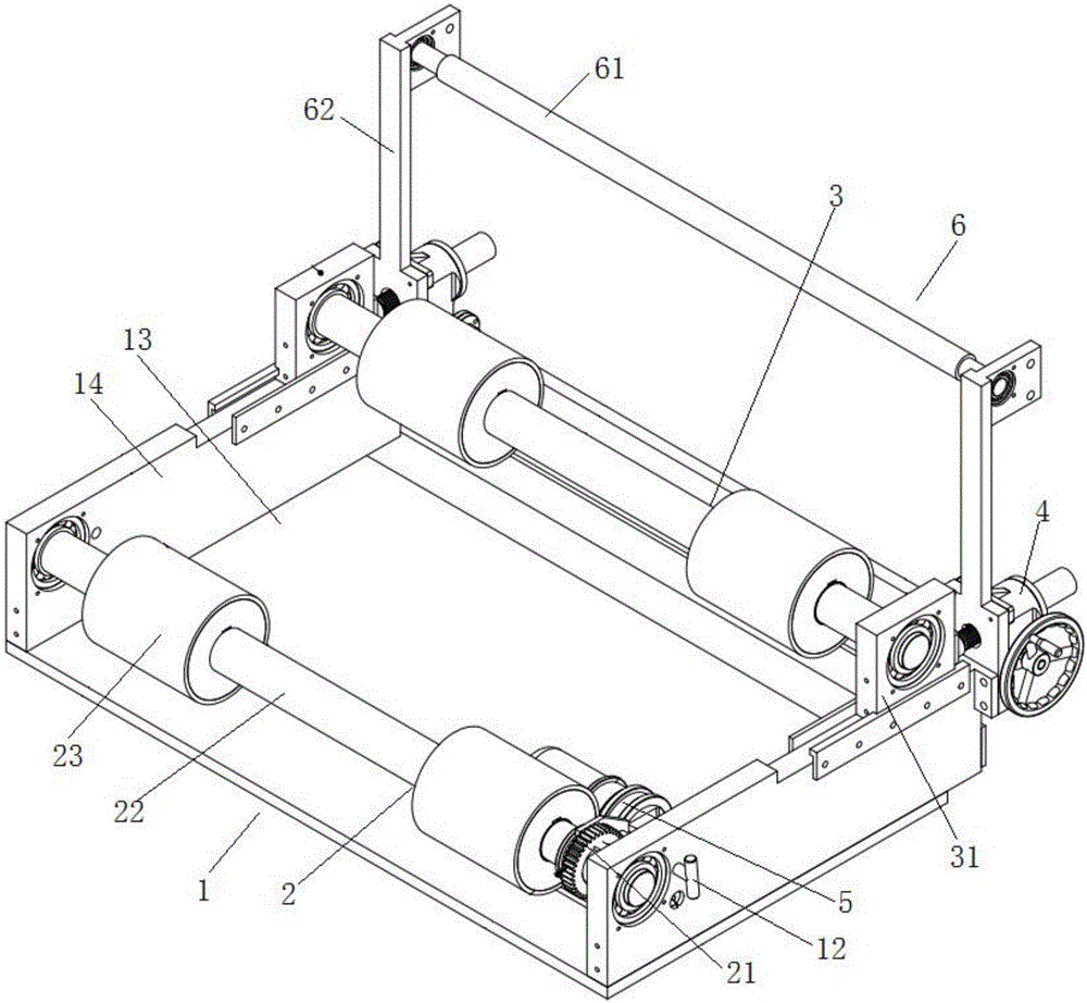
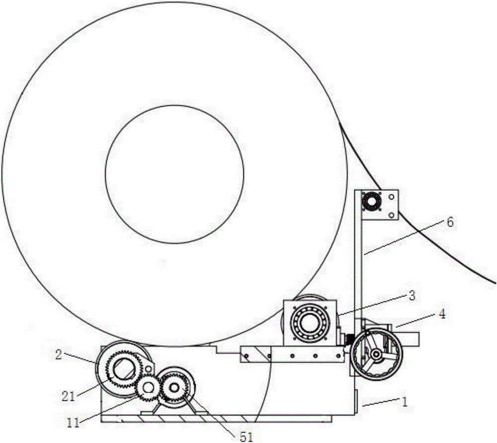
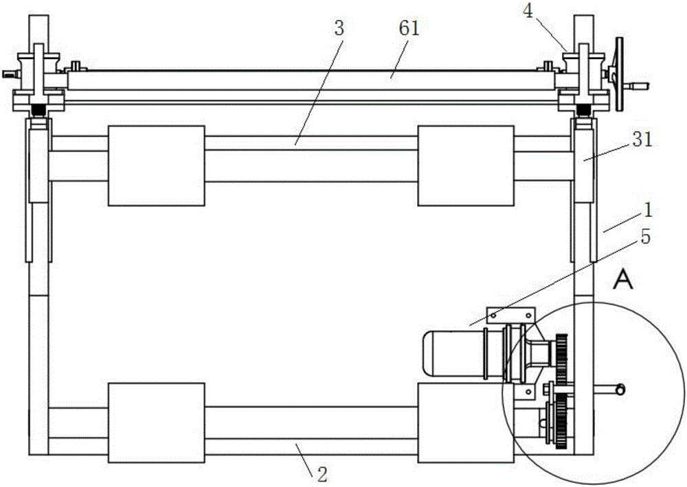
[0037] Example: such as Figures 1 to 5 As shown, the coil unwinding and unwinding machine of this embodiment includes a mounting bracket 1, a first roller shaft assembly 2, a second roller shaft assembly 3, a power pushing device 4 and a rotation driving device 5;

[0038] The above-mentioned first roller shaft assembly 2 and the second roller shaft assembly 3 are arranged horizontally and spaced in parallel, the above-mentioned first roller shaft assembly 2 is rotatably mounted on the above-mentioned mounting bracket 1; the two ends of the above-mentioned second roller shaft assembly 3 pass through the bearing seat 31 is slidably installed on the above-mentioned mounting bracket 1;

[0039] The above-mentioned power pushing device 4 is installed on the above-mentioned installation bracket 1, and can push the second roller shaft assembly 3 to move horizontally along the installation bracket 1 to approach or move away from the first roller shaft assembly 2 through the driving ...


PUM


Abstract

The invention relates to an uncoiling and discharging machine for coiled plates. A first drum shaft assembly and a second drum shaft assembly are transversely arranged at intervals in parallel; the first drum shaft assembly is rotatably mounted on a mounting support; two ends of the second drum shaft assembly are slidably mounted on the mounting support through bearing blocks; power pushing devices are mounted on the mounting support, and can push the second drum shaft assembly to move horizontally along the mounting support so as to be close to or away from the first drum shaft assembly; a rotation driving device is mounted on the mounting support; a driving gear is arranged at a driving end of the rotation driving device; an intermediate gear is arranged on the mounting support and is engaged with the driving gear; the first drum shaft assembly is provided with a driven gear; and the driven gear can move along the first drum shaft assembly in the axial direction so that the driven gear is engaged with or separated from the intermediate gear. The uncoiling and discharging machine for coiled plates has the advantages that the structure is simple, the first drum shaft assembly is adjusted to actively or passively discharge materials according to usage requirements, the distance between the first drum shaft assembly and the second drum shaft assembly is adjusted, and therefore, the uncoiling and discharging machine for coiled plates is flexible and convenient to use.

Description

technical field [0001] The invention relates to coiling and discharging equipment, in particular to a coiling and uncoiling discharging machine. Background technique [0002] Most of the existing coiling and unwinding equipment fix various specifications of coiling materials on various mandrels in various forms, and then uncoil and unwind the coiled materials. Often a mandrel It is also difficult to adapt to coiling materials of different specifications, and the distance between the mandrels is fixed, which cannot adapt to coiling materials of various specifications. At the same time, it cannot be adjusted to realize active or passive unwinding operations according to actual use requirements. Therefore, Its use has many inconveniences. Contents of the invention [0003] The technical problem to be solved by the present invention is to provide a plate uncoiling and unwinding machine, which effectively overcomes the defects of the prior art. [0004] The technical solution...

Claims


Application Information

Patent Timeline
IPC IPC(8): B65H16/08B65H16/10B65H23/26
CPCB65H16/08B65H16/106B65H23/26B65H2701/1133
Inventor 徐全权胡成苏朱坤先
Owner 安陆市华誉金属网机制造有限公司
Why Eureka
Try Eureka