Cotton-cloth-attachment-yarn winding device bringing convenience to position transformation

A yarn and cotton fabric technology, applied in the field of cotton fabric laminating yarn winding equipment, can solve the problems affecting the sliver weight and carding effect in the carding process, affecting the consistency of the yarn quality in the process, affecting the production process, etc. To achieve reasonable design, improve anti-sticking effect, improve the effect of stability

Inactive Publication Date: 2017-05-31
苏州市朗润纺织科技有限公司
View PDF15 Cites 5 Cited by
  • Summary
  • Abstract
  • Description
  • Claims
  • Application Information

AI Technical Summary

Problems solved by technology

In the spinning production process, due to seasonal climate, workshop temperature and humidity, raw materials and equipment, etc., the cotton laps produced in the workshop often have sticking during the winding process. After sticking, it will directly affect the carding process. The weight of sliver and carding effect will ultimately affect the consistency of yarn q...

Method used


Image

  • Cotton-cloth-attachment-yarn winding device bringing convenience to position transformation
  • Cotton-cloth-attachment-yarn winding device bringing convenience to position transformation
  • Cotton-cloth-attachment-yarn winding device bringing convenience to position transformation

Examples


Embodiment Construction

[0015] In order to make the technical means, creative features, goals and effects achieved by the present invention easy to understand, the present invention will be further described below in conjunction with specific embodiments.

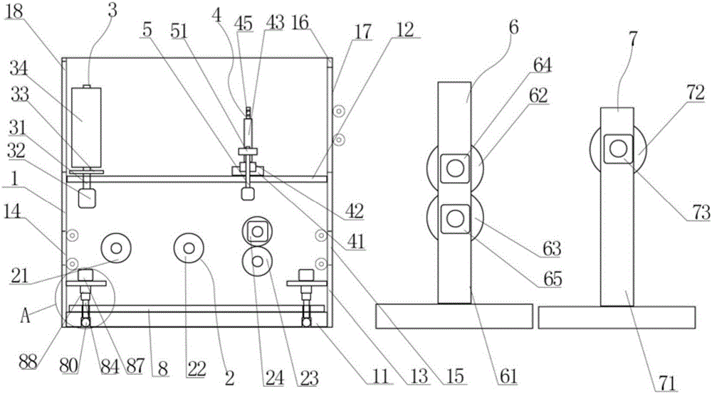
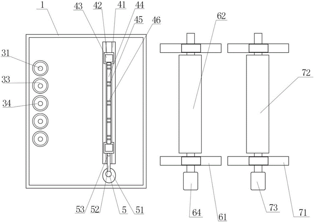
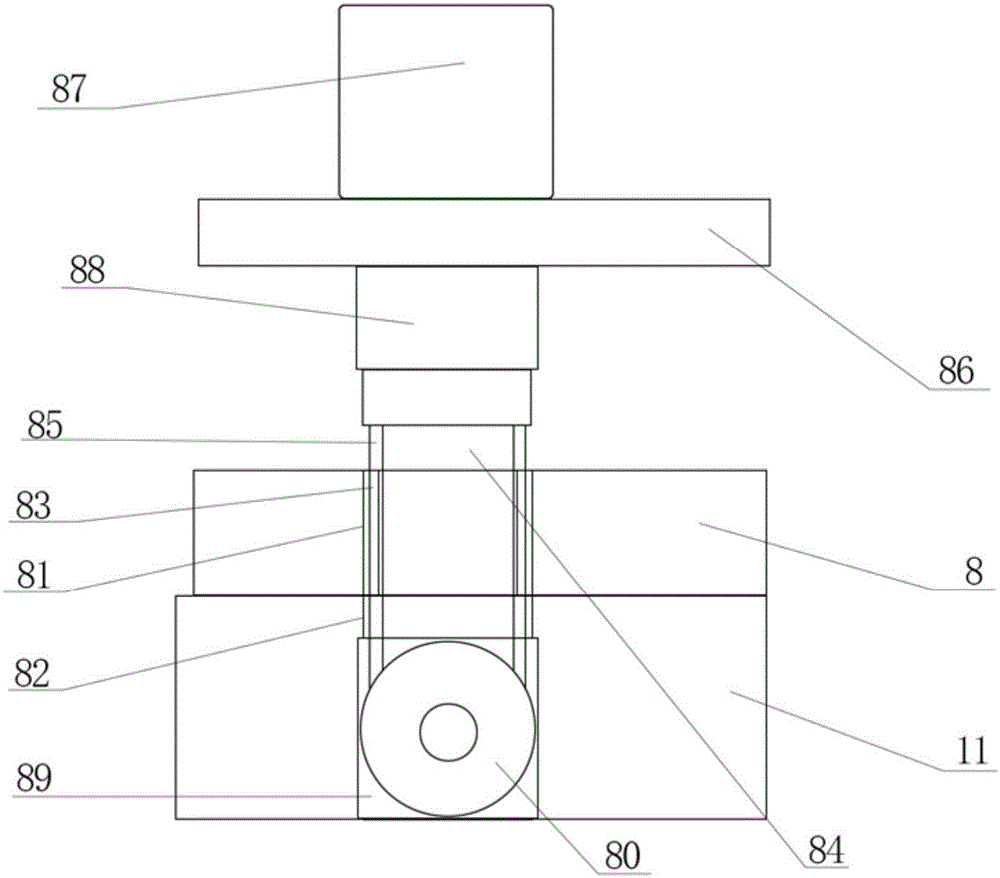
[0016] like Figure 1 to Figure 3 As shown, a cotton cloth laminating yarn roll 34 coiling device that is convenient for position change of the present invention includes a frame 1, a bottom plate 11 is provided at the bottom of the frame 1, a horizontal plate 12 is provided at the middle of the frame 1, and a frame The side of 1 includes the lower side plate 13 arranged between the bottom plate 11 and the horizontal plate 12 and the upper side plate 16 arranged on the upper part of the horizontal plate 12. A yarn unwinding assembly 3 is arranged on the top, and one side of the yarn unwinding assembly 3 is provided with a swing mechanism 4, and one side of the frame 1 is respectively provided with a pressing mechanism 6 and a winding mechanism 7, ...


PUM


Abstract

The invention discloses a cotton-cloth-attachment-yarn winding device bringing convenience to position transformation. The cotton-cloth-attachment-yarn winding device comprises a machine frame, a bottom plate is arranged at the bottom of the machine frame, a transverse plate is arranged in the middle of the machine frame, a cotton roll conveying assembly is arranged at the upper portion of the bottom plate, a yarn unwinding assembly is arranged on the transverse plate, a swinging mechanism is arranged on one side of the yarn unwinding assembly, a pressing mechanism and a winding mechanism are respectively arranged on one side of the machine frame, fixing strips are horizontally arranged on two sides of the top of the bottom plate respectively, through grooves are formed in the two ends of the fixing strips, through holes corresponding to the through grooves are formed in the bottom plate in a penetrating mode, four sliding strips are arranged on the side faces of the through grooves at equal intervals, movable rods are arranged in the through grooves, four sliding grooves corresponding to the sliding strips are arranged on the side faces of the movable rods, supporting plates are horizontally arranged at the upper portions of the fixing strips, hydraulic cylinders are arranged at the tops, of the through grooves, on the supporting plates, stretchable columns are arranged at the bottoms of the hydraulic cylinders and connected with the movable rods, circular grooves are formed in the portions, located at the lower portions of the through holes, in the bottom plate, and universal wheels are arranged in the circular grooves and connected with the movable rods.

Description

technical field [0001] The invention relates to the technical field of textiles, in particular to a cotton laminating yarn winding device which is convenient for position change. Background technique [0002] The original meaning of textile is taken from the general term of spinning and weaving, but with the continuous development and improvement of the textile knowledge system and subject system, especially after the emergence of non-woven textile materials and three-dimensional composite weaving technologies, the current textile is not only a traditional Hand spinning and weaving also include garment, industrial and decorative textiles produced by non-woven technology, modern three-dimensional weaving technology, and modern electrostatic nano-netting technology. In the spinning production process, due to seasonal climate, workshop temperature and humidity, raw materials and equipment, etc., the cotton laps produced in the workshop often have sticking during the winding pro...

Claims


Application Information

Patent Timeline
IPC IPC(8): B65H54/28B65H54/72B65H57/24B65H49/24B65H51/08
CPCB65H49/24B65H51/08B65H54/28B65H54/72B65H57/24B65H2701/31
Inventor 朱峰
Owner 苏州市朗润纺织科技有限公司
Why Eureka
Try Eureka