Core taking mechanism for roll paper core recovery

A technology of web and paper core, applied in the field of coring mechanism for web core recycling, can solve the problems of inaccurate positioning of paper core, high cost, waste of cost and work efficiency, so as to improve work efficiency and core removal Variety of specifications and precise position

Active Publication Date: 2017-05-31
临澧金华天机械制造有限公司
6 Cites 1 Cited by

AI-Extracted Technical Summary

Problems solved by technology

[0003] In the prior art, most of the paper cores are taken manually, which has low efficiency, poor effect and high cost
However, there are also some coring mechanisms, but due to structural design def...

Abstract

The invention discloses a core taking mechanism for roll paper core recovery. The mechanism comprises an automatic overturning part, an automatic arranging part, an automatic speed adjusting part, a core taking part, a negative-pressure part, a paper cutting falling part, a core falling return part and a core taking pressing part which are fixed on a frame, wherein a discharge end of the automatic overturning part is connected with a feed end of the automatic arranging part; the automatic speed adjusting part is connected to a discharge end of the automatic arranging part; the core taking part is fixed on the negative-pressure part above a discharge end of the automatic speed adjusting part; the paper cutting falling part is arranged on one side of the core taking part; the core falling return part and the core taking pressing part are positioned around the negative-pressure part; and the core falling return part and the core taking pressing part are spaced by multiple stations. The mechanism integrates such functions of automatic overturning, automatic sorting, automatic core taking and paper core separation, realizes full-automatic core taking, is precise in roll paper positioning, is various in core taking specifications, improves the working efficiency, and saves the cost.

Application Domain

Technology Topic

Paper sheetPaper cut +1

Image

  • Core taking mechanism for roll paper core recovery
  • Core taking mechanism for roll paper core recovery
  • Core taking mechanism for roll paper core recovery

Examples

  • Experimental program(1)

Example Embodiment

[0037] The present invention will now be described in detail with reference to the drawings and embodiments.
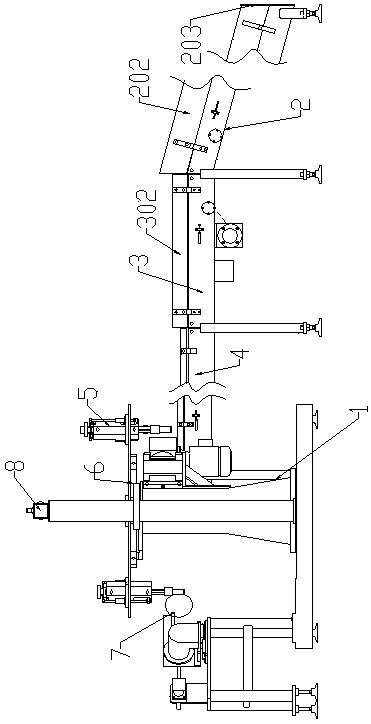
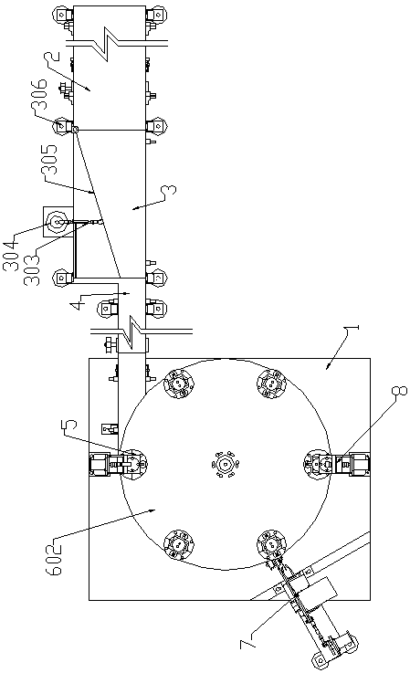
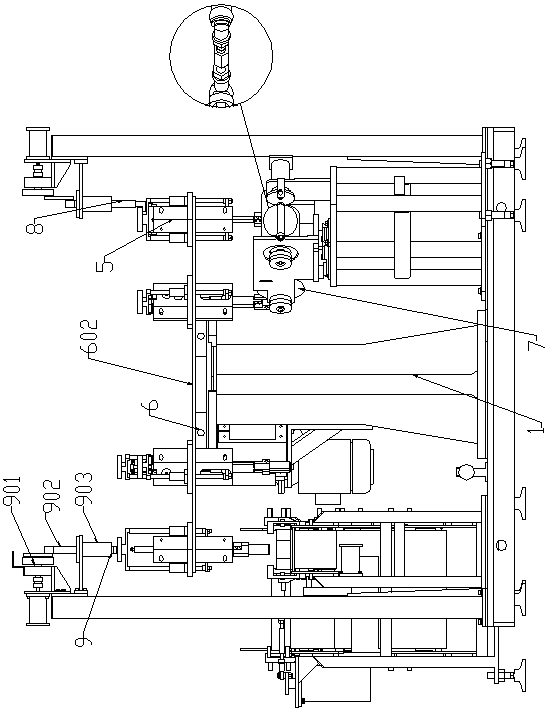
[0038] Such as Figure 1-3 As shown, the core taking mechanism for roll paper core recovery of the present invention includes an automatic turning part 2, an automatic arrangement part 3, an automatic speed regulating part 4, a core taking part 5, and a negative pressure part 6 fixed on the frame 1. , Cut-off part 7, core removal reset part 8, core pressing part 9, in which the discharge end of the automatic turning part 2 is connected to the feeding end of the automatic arrangement part 3, and the automatic speed regulation part 4 is connected to the automatic arrangement part 3 At the discharging end, the core part 5 is fixed on the negative pressure part 6 above the discharging end of the automatic speed regulation part 4, the cut-off part 7 is arranged on one side of the core part 5, the core removal reset part 8, the core The pressing parts 9 are respectively located on both sides of the negative pressure part 6 and the core removal reset part 8 and the core removal pressing part 9 are separated by a plurality of stations.
[0039] Such as Figure 4 Among them, the automatic turning part 2 includes an inclined belt section 201, an inclined side baffle 202 on both sides of the inclined belt section 201, and a bottom baffle 203 at the bottom of the inclined belt section 201. The inclined side baffles 202 and bottom baffles 203 on both sides block Tilt the web on the belt section 201 to prevent it from falling. When working, the inclined angle of the inclined belt section 201 is set to 15°. When the roll paper is poured on the inclined belt section 201, because the axis of the roll paper is parallel to the inclined belt section 201, the angle of the roll paper and the inclined belt section 201 The friction is too small to overcome its own gravity, so it will not climb, but only roll on the inclined belt section 201. When the roll paper stands on the inclined belt section 201, because the axis of the roll paper is perpendicular to the belt 201, the contact area between the paper and the inclined belt section 201 increases and the friction between each other can overcome the roll paper itself. Gravity, so that the web can climb with the belt. Those rolls that are not perpendicular to the inclined belt section 201 will be rolled up under the impact of the rest of the roll paper or other external forces until the axis of the roll paper is perpendicular to the inclined belt section 201 to climb, thus reaching the roll paper Automatic rollover function.
[0040] Such as Figure 5 The automatic arrangement part includes a swing rod 303, an arrangement motor 304, a baffle 305, a central shaft 306, a first horizontal belt section 301, and a horizontal side baffle 302. One end of the swing rod 303 is fixed on the output shaft of the arrangement motor 304 , The arrangement motor 304 is fixed on the frame 1, the other end of the swing rod 303 is connected to the baffle 305, one end of the baffle 305 is sleeved on the central axis 306 and rotates around the central axis 306, and the bottom of the baffle 305 is located at the first Above a horizontal belt section 301. During operation, the arrangement motor 304 drives the swing rod 303 to swing at a constant speed at a speed of about 30 revolutions per minute, thereby driving the baffle 305 to rotate around the central axis 306. Under the action of the baffle 305, with the rotation of the first horizontal belt section 301, the roll paper is leaned to one side, thus realizing the automatic arrangement of the roll paper.
[0041] Such as Image 6 Among them, the automatic speed regulation part includes a second horizontal belt section 401, a third horizontal belt section 402, two photoelectric switches 403 installed at the head and end of the third horizontal belt section 402, an arc retaining ring 404, a spring 405, and a Speed ​​motor 406, in which the arc retaining ring 404 is fixed at the end of the third horizontal belt section 402, a spring 405 is connected between the arc retaining ring 404 and the frame 1 on the side of the third horizontal belt section 402, and the speed regulating motor 406 Fixed on the rack. The cam divider 605 sets the working speed. Two photoelectric switches 403 are installed at the head and end of the third horizontal belt section 402 to detect whether there is a roll of paper passing through each position. The time difference detected by the two photoelectric switches It also reacts to the PLC (model S7226). The PLC adjusts the speed adjustment motor 406 to adjust the speed. When the photoelectric switch 403 at the end cannot detect the web, the PLC controls the speed adjustment motor 406 to slow down the second horizontal belt section 401 When the photoelectric switch 403 at the head end cannot detect the roll paper, the PLC controls the speed regulating motor 406 to stop. The speed of the third horizontal belt section 402 is twice as fast as the speed of the second horizontal belt section 401, and the speed is increased to avoid jamming of the roll paper. When the roll paper reaches the arc retaining ring 404, because the spring 405 pulls the arc retaining ring 404 and blocks the roll paper, the roll paper stays on the arc retaining ring 404. And when Figure 7 The suction head 508 in the middle is inserted into the roll paper core. As the cam divider 605 drives the rotation of the big turntable 602, the roll paper breaks through the tension of the spring 404, and the suction head 508 drives the roll paper away. At the same time, as the spring 405 returns, The arc retaining ring 404 also returns to the original position, blocking the next roll of paper.
[0042] Such as Figure 7 , Picture 8 Among them, the core part 5 includes a positioning cylinder 501, a small disc 502, a linear bearing 503, a linear shaft 504, a connecting rod 505, two scissors handles 506, two connecting blocks 507, two suction heads 508, and a roller 510, The small disc 502 is connected to the linear bearing 503 through the connecting rod, the linear bearing 503 is fixed on the positioning cylinder 501, the linear shaft 504 is sleeved on the linear bearing 503, the lower end of the linear shaft 504 is connected to one end of the connecting rod 505, and two connecting blocks 507 The upper ends of the two scissors handles 506 are connected to each other. A return spring 509 is connected between the top ends of the two scissors handles 506. The lower ends of the two connecting blocks 507 are correspondingly connected to two suction heads 508, and the two connecting blocks 507 are hinged. The other end of the connecting rod 505 is fixed on the hinge point of the two connecting blocks 507; a groove is opened on the inner side of each scissors handle 506, and the grooves on the two scissors handles 506 are misaligned up and down; in the positioning cylinder A roller 510 located between two scissors handles 506 is fixed on the 501 through a fixed shaft. When in use, the pressing block 903 in the coring pressing part 9 presses down the small disc 502, and drives the linear bearing 503 to press the linear shaft 504 to move downward, thereby driving the connecting rod 505 to press down, from Picture 8 It can be seen that the downward movement of the connecting rod 505 will drive the two scissors handles 506 to move downward. And because of the special shape of the scissors formed by the scissors handle 506, the connecting block 507 and the suction head 508 , In the process of falling, the distance between the two suction heads 508 connected under the two scissors handles 506 will first gradually decrease from large to small and then suddenly increase, supporting the roll paper core until the suction head 508 is inserted into the roll. The purpose of the paper core. At the same time, there is negative pressure on the suction head 508, which can absorb the paper core so that it will not fall off.
[0043] Such as Picture 9 , Picture 10 The negative pressure part 6 includes a negative pressure plate 601, a large turntable 602, a trachea 603, and a trachea seat 604. The negative pressure plate 601 is composed of an inner ring 6011 and an outer ring 6012, and the inner ring 6011 is fixed on the frame 1. The top of the outer ring 6012 is connected to the big turntable 602 and the outer ring 6012 rotates synchronously with the big turntable 602. The mounting shaft of the big turntable 602 is connected to the cam divider 605; the trachea seat 604 is fixed on the outer ring 6012 and the trachea seat 604 is fixed The root trachea 603, wherein the other end of the trachea 603 is connected to the suction head 508 of the coring part. When in use, because the inner ring 6011 of the negative pressure plate 601 only has negative pressure in the working part, only the part where the outer ring 6012 and the inner ring 6011 are connected has negative pressure, so as the large turntable 602 rotates, the negative pressure is controlled The presence or absence.
[0044] Such as Picture 11 , Picture 12 The cut-off part 7 includes a mounting plate 701, a double linear guide 702, a cutter head 703, a narrow V belt 704, a blowing nozzle 705, a first motor 706, and a second motor 707. The first motor 706 is connected to The mounting plate 701 is connected. The bottom of the mounting plate 701 is equipped with a pulley that matches with the double linear guide 702. The double linear guide 702 is fixed on the frame 1, the cutter head 703 is fixed on the mounting plate 701, and the cutter head 703 and the second motor The 707 is connected by a narrow V-belt 704. A blowing nozzle 705 is fixed on the mounting plate 701 at the front and back of the cutter head 703. The blowing nozzle 705 is connected to the air pipe seat 604 on the negative pressure plate 601 through a gas pipe. With the rotation of the first motor 706, the connecting rod drives the mounting plate 701 to reciprocate on the double linear guide 702, which drives the forward and backward movement of the cutter head 703. At the same time, the cutter head 703 is passed through the narrow V belt 704 by the second motor 707. The connection ensures that the cutter head 703 always rotates stably and at a high speed. The blade on the cutter head 703 separates the paper core from the roll paper. The blowing nozzle 705 is connected to the air pipe and blows against the cutter head 703 through positive pressure to blow off the paper, but due to the suction of negative pressure, the paper core will not fall off, thus achieving the function of separating the paper core. This process and the coring process are carried out simultaneously.
[0045] Such as Figure 13 As shown, the stripping reset part 8 includes a reset motor 801, a small turntable 802, and a lifting block 803. The reset motor 801 is fixed on the frame 1 and the output shaft of the reset motor 801 is connected to the small turntable 802. The small turntable 802 is connected with a connecting rod. Lifting block 803, the bottom of the lifting block 803 has an "L" shape and hooks the small disk 502 of the core-taking part 5. After the negative pressure is broken, the reset motor 801 rotates to drive the small turntable 802 to rotate. Through two connecting rods, the lifting block 803 is driven to rise, and the small disk 502 in the core-taking part is pulled up, and the attached Figure 7 Similarly, the distance between the two suction heads 508 gradually becomes smaller and then suddenly becomes larger, the paper core falls off, and the core removal part is reset. The same process and coring process and attached Picture 11 The process of cutting off the paper is carried out simultaneously.
[0046] Such as image 3 As shown, the coring pressing part 9 includes a pressing power plate 901, a lifting shaft 902, and a pressing block 903. The pressing power plate 901 is of a hand-cranked type and is fixed on the frame 1, and the pressing power plate 901 is hinged at an off-center position. The bottom of the lifting shaft 902 is fixed with a pressing block 903. When in use, the power plate 901 is pressed manually, and the lifting shaft 902 moves downward or upward under the action of the eccentric force, which drives the pressing block 903 to press the small disc 502 or reset.
[0047] In this embodiment, the core part 5 is fixed on the large turntable 602 of the negative pressure part 6. A total of 6 core parts 5 are fixed on the large turntable 602 in the circumferential direction, and the core pressing part 9 works There are two working positions spaced between the core removal and reset part 8.

PUM

no PUM

Description & Claims & Application Information

We can also present the details of the Description, Claims and Application information to help users get a comprehensive understanding of the technical details of the patent, such as background art, summary of invention, brief description of drawings, description of embodiments, and other original content. On the other hand, users can also determine the specific scope of protection of the technology through the list of claims; as well as understand the changes in the life cycle of the technology with the presentation of the patent timeline. Login to view more.

Similar technology patents

Classification and recommendation of technical efficacy words

  • Accurate location
  • Easy to separate

Indoor location identification system

InactiveUS20050143091A1Accurate locationEmergency connection handlingConnection managementSTI OutpatientSystem definition
Owner:CORNING MOBILEACCESS

Enhancing filtration yields in tangential flow filtration

InactiveUS6350382B1High precision separationEasy to separateLiquid separation auxillary apparatusMembranesEngineeringPeak pressure
Owner:PARKER INTANGIBLES LLC

Process and apparatus for treating tailings

ActiveUS20050150844A1Easy to separateMaximize efficiencyWorking-up pitch/asphalt/bitumen by selective extractionSolid separationSolventOil sands
Owner:TRUENORTH ENERGY CORP
Why Eureka
Try Eureka