Cutting system and cutting method

A technology of cutting system and cutting method, which is applied in glass cutting device, glass manufacturing equipment, glass production, etc., can solve the problem of different warpage of glass substrate cutting line position, unsatisfactory cutting flatness, and sharp cutting yield Reduce and other problems, to achieve the effect of improving cutting compatibility, improving cutting accuracy and cutting yield, and reducing costs

Active Publication Date: 2017-05-31
BOE TECH GRP CO LTD +1
View PDF3 Cites 5 Cited by
  • Summary
  • Abstract
  • Description
  • Claims
  • Application Information

AI Technical Summary

Problems solved by technology

[0005] There are obvious restrictive factors in this method. First, with the long-term continuous use of the support table, the laser focus point will inevitably drift, which will affect the cutting accuracy and cutting quality of the glass substrate.
Secondly, when producing substrates with different thicknesses, two main problems are often encountered: 1. After the substrate is thinned, the flatness required for cutting is often not well satisfied; 2. The warpage of the cutting line position of the glass substrate is different. The laser focal length cannot meet the cutting requirements of different warpage positions at the same time, resulting in a sharp drop in cutting yield

Method used


Image

  • Cutting system and cutting method
  • Cutting system and cutting method
  • Cutting system and cutting method

Examples


Embodiment 1

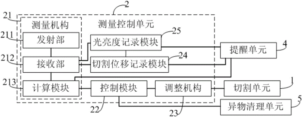
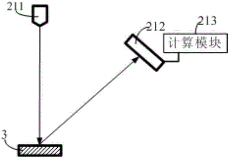
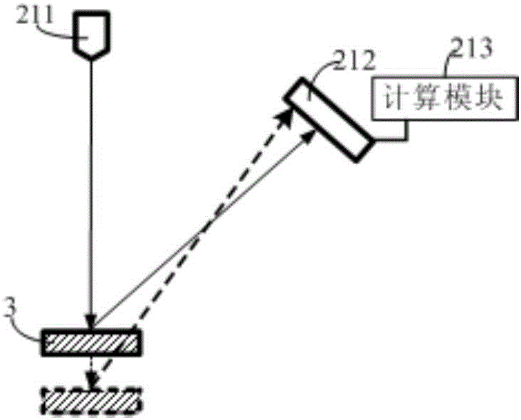
[0052] This embodiment provides a cutting system, such as figure 1 As shown, it includes a cutting unit 1 for laser cutting the display substrate, and also includes a measurement control unit 2 for measuring the distance between the laser focus of the cutting unit 1 and the surface of the display substrate in real time, and when the measurement result is not zero , adjust the distance between the laser focus and the surface of the display substrate to zero in real time.

[0053] By setting the measurement control unit 2, the laser focal point of the cutting unit 1 can be kept just falling on the surface of the display substrate during the cutting process, thereby not only avoiding the impact of the flatness of the base platform used to support the display substrate during cutting on the cutting accuracy and The influence of the cutting quality, and avoid the influence of the flatness of the display substrate itself on the cutting accuracy and cutting quality, especially avoid ...

Embodiment 2

[0083] This embodiment provides a cutting system. The difference from Embodiment 1 is that the measurement control unit in this embodiment does not include a cutting displacement recording module and a brightness recording module.

[0084] Correspondingly, the cutting method in this embodiment also does not include the steps of recording the displacement position data of the laser focus of the cutting unit along the cutting line on the display substrate and recording the brightness data of each displacement position of the laser focus on the cutting line .

[0085] Other structural configurations of the cutting system and other steps of the cutting method in this embodiment are the same as those in Embodiment 1, and will not be repeated here.

[0086] Beneficial effects of Embodiment 1-2: The cutting system provided by Embodiment 1-2, by setting the measurement control unit, can keep the laser focus of the cutting unit just falling on the surface of the display substrate durin...


PUM


Abstract

The invention provides a cutting system and a cutting method. The cutting system comprises a cutting unit and a measurement control unit, wherein the cutting unit is used for cutting a display substrate with laser; and the measurement control unit is used for measuring the distance between a laser focus of the cutting unit and the surface of the display substrate in real time, and when the measurement result is not zero, adjusting the distance between the laser focus and the surface of the display substrate to zero in real time. The cutting system not only avoids the influence of flatness of an abutment for supporting the display substrate on cutting precision and cutting quality, but also avoids the influence of flatness of the display substrate on cutting precision and cutting quality, particularly avoids the influence of warpage difference caused by thickness difference of different positions of the display substrate along a cutting line on cutting precision and cutting quality, effectively improves the cutting compatibility on various display substrates having different sizes and thicknesses, reduces the cost, and simultaneously improves the cutting precision and the cutting yield.

Description

technical field [0001] The invention relates to the technical field of display product manufacturing, in particular to a cutting system and a cutting method. Background technique [0002] With the increasingly high requirements of end customers for electronic products, the market is enthusiastic about ultra-thin products, especially the pursuit of high resolution, light weight and ultra-thin large-size organic electroluminescent display (OLED TV). The thickness of the panel is also developing towards thinner and thinner. [0003] With the continuous reduction of the thickness of the glass substrate, its thickness is constantly developing from 0.7mm, 0.5mm to 0.4mm, 0.3mm and other thinner directions. It is inevitable that the cutting requirements for large-size substrates will also become higher and higher. In the case of the same substrate size, the thinner the thickness of the substrate, the greater the warpage of the substrate itself, and the greater the sag under the su...

Claims


Application Information

Patent Timeline
Patent Type & Authority Applications(China)
IPC IPC(8): C03B33/02C03B33/037
CPCC03B33/0222C03B33/037Y02P40/57
Inventor 江昌俊
Owner BOE TECH GRP CO LTD
Why Eureka
Try Eureka