Catalytic cracking reactor

A catalytic cracking and reactor technology, applied in the field of reactors, can solve the problems of bulky and difficult reactor equipment, and achieve the effects of reducing overcracking, reducing reaction time, and suppressing backmixing

Inactive Publication Date: 2017-05-31
彭州市运达知识产权服务有限公司
View PDF0 Cites 0 Cited by
  • Summary
  • Abstract
  • Description
  • Claims
  • Application Information

AI Technical Summary

Problems solved by technology

However, there is a problem that the reactor equipment i

Method used


Image

  • Catalytic cracking reactor

Examples


Embodiment Construction

[0022] Below in conjunction with accompanying drawing, the present invention is described in detail.

[0023] In order to make the object, technical solution and advantages of the invention clearer, the present invention will be further described in detail below in conjunction with the accompanying drawings and embodiments. It should be understood that the specific embodiments described here are only used to explain the present invention, not to limit the present invention.

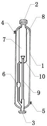
[0024] Such as figure 1 As shown, a catalytic cracking reactor includes an inner tube 7 sheathed in an outer tube 1 , the top and bottom of the outer tube 1 are open, and the side walls of the outer tube 1 are relatively provided with a number of circulation ports. The number of circulation ports is 2, which are respectively upper circulation port 4 and lower circulation port 5. The upper circulation port 4 is located at the top of the outer tube 1, and the lower circulation port 5 is located at the bott...


PUM


Abstract

The invention discloses a catalytic cracking reactor, and belongs to the field of petrochemical engineering industry. The catalytic cracking reactor comprises an internal pipe, and an external pipe used for sleeving the internal pipe; the top end and the bottom end of the external pipe are provided with openings; the side wall of the external pipe is relatively provided with a plurality of circulation ports. The catalytic cracking reactor is capable of shortening reaction time, increasing oil agent contact efficiency, inhibiting backmixing, reducing equipment dead angle, reducing coking amount as far as possible, shortening standing time of oil gas in bed layer space, and reducing intermediate product overcracking in transition process from a fluidized bed reactor to a riser reactor and a down-flow reactor.

Description

technical field [0001] The invention relates to a reactor, in particular to a catalytic cracking reactor. Background technique [0002] Since the 1950s, the catalytic cracking process in the petrochemical industry has made great progress, and this process plays a pivotal role in the refining process. At present, in the field of petrochemical industry, the traditional catalytic cracking reactor adopts the form of riser reaction. The riser reaction method has the problem that the atomized raw material cannot be fully mixed with the high-temperature catalyst in the reactor for contact reaction. In the riser reactor, the linear velocity of the oil and gas is higher than that of the catalyst, resulting in carbonization of the catalyst. Back-mixing is formed due to slippage; and the reaction time of the riser reactor is long, generally around 4s. Too long reaction time has a great influence on product distribution and product properties. For this reason, in the 1990s, a gas-soli...

Claims


Application Information

Patent Timeline
IPC IPC(8): C10G11/18B01J8/24
CPCC10G11/18B01J8/24B01J2208/00194B01J2208/00991C10G2400/02
Inventor 张进
Owner 彭州市运达知识产权服务有限公司
Why Eureka
Try Eureka