Waste heat recovery device of gas-based shaft furnace and gas-based shaft furnace
A technology of waste heat recovery device and gas-based shaft furnace, which is applied in the direction of shaft furnace, furnace, furnace type, etc., can solve the problems of energy waste, the sensible heat of shaft furnace top gas is not effectively used, etc., so as to reduce energy loss and improve Energy efficiency, stress reduction effect
- Summary
- Abstract
- Description
- Claims
- Application Information
AI Technical Summary
Problems solved by technology
Method used
Image

Examples
Embodiment 1
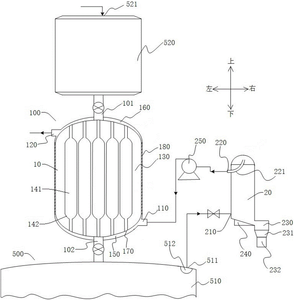
[0059] Such as figure 1 and figure 2 As shown, the gas-based shaft furnace 500 includes a furnace body 510 and a material bin 520, the furnace body 510 is used for the reduction of iron-containing raw materials, and the material bin 520 can add heat source materials for the furnace body 510, for example, the materials can be oxidized pellets, etc. To provide heat for the reduction process of raw materials. It can be understood that, during the reduction process, the generated top gas has a relatively high temperature, and the temperature of the top gas discharged from the exhaust port 511 is about 450°C.
[0060] The waste heat recovery device 100 can recover and utilize the heat of the high-temperature top gas discharged from the gas-based shaft furnace 500, so as to improve energy utilization rate, save energy and protect the environment. Such as figure 1 and figure 2 As shown, the waste heat recovery device 100 includes: a heat exchange chamber 10 , a dust discharge d...
Embodiment 2
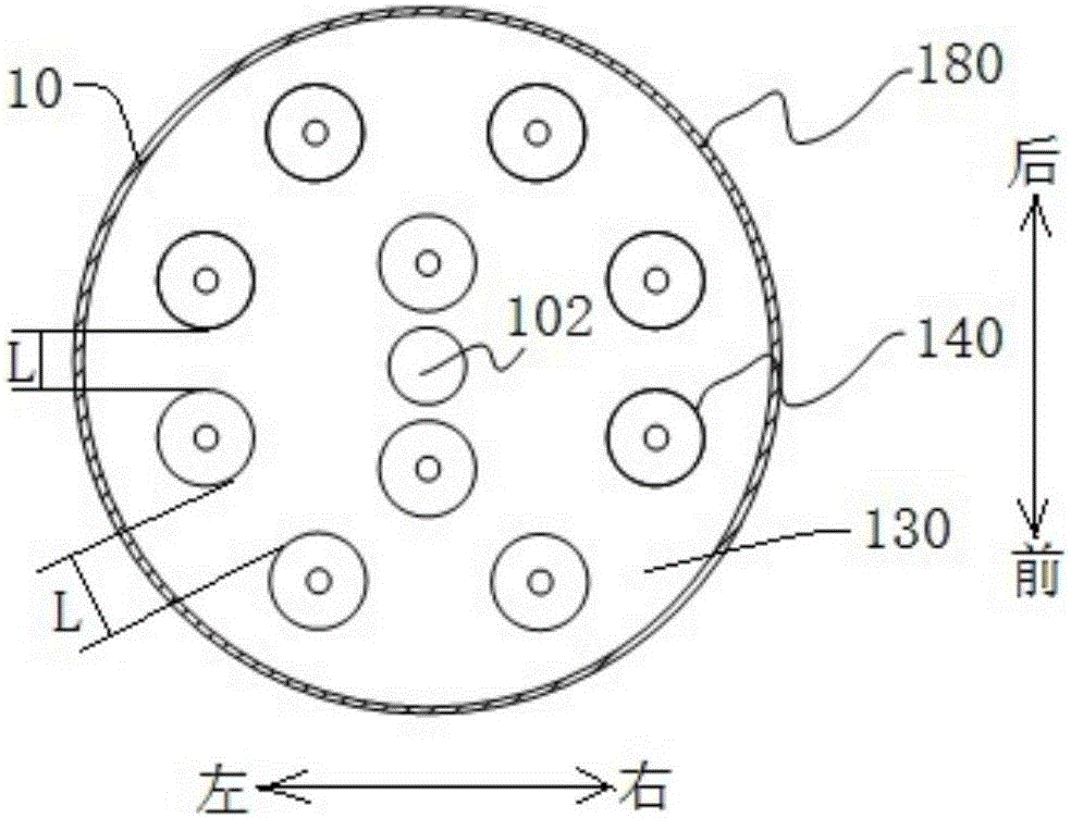
[0073] The difference from the first embodiment is that in this embodiment, the high-temperature top gas flows into the heat exchange chamber 10 at a flow rate of 568767Nm3 / h. The gas channels 140 are arranged in 40 rows, and the diameter of the expansion section 141 of the gas channels 140 is 100 mm. The temperature field distribution of each area in the heat exchange chamber 10 is as follows: at the bottom of the heat exchange chamber 10, the temperature in the heat exchange chamber 10 at the small diameter area of the gas channel 140 is about 443°C; in the middle of the heat exchange chamber 10, the temperature in the gas channel The temperature in the heat exchange chamber 10 at the expansion section 141 area of 140 is 155°C-448°C; at the upper part of the heat exchange chamber 10, the temperature in the heat exchange chamber 10 at the small diameter area of the gas channel 140 is 30°C-150°C ℃.
[0074] Therefore, by increasing the number of gas passages 140, the he...
PUM
 Abstract
Description
Claims
Application Information