
Bobbin and spindle connector

A technology of connectors and spindles, which is applied in the direction of textiles and papermaking, can solve the problems of increasing the yarn breakage rate, increasing the vibration of the main machine, and the limitation of the spindle speed, so as to reduce the yarn breakage rate and reduce the moment of inertia , to meet the effect of high-speed spinning

Active Publication Date: 2017-05-31
晋中经纬恒腾纺机有限公司
View PDF22 Cites 2 Cited by
  • Summary
  • Abstract
  • Description
  • Claims
  • Application Information

AI Technical Summary

Problems solved by technology

[0003] With the advancement of technology, the spinning frame collective doffing system is often used in the yarn making process to reduce the cost of yarn making, reduce labor intensity and meet the application of advanced fine-bonding technology; while the traditional spinning frame bobbin and spindle In the connection method, the bobbins are fixed and cannot be pulled out, and this connection method can no longer meet the requirements of collective doffing and collective extubation; in order to meet the requirements of collective doffing and extubation, at present, aluminum casing spindles have been produced, using The bobbin and the spindle are positioned, connected, and rotated synchronously by means of spring tension; the cost of the spindle using the aluminum sleeve is greatly increased, and the addition of the aluminum sleeve increases the moment of inertia of the spindle and the swing of the bobbin Large, increase the vibration of the main machine, limit the spindle speed and increase the yarn breakage rate; if the collective doffing transformation is carried out on the original spinning frame, it is necessary to replace the original (polished rod) spindle with an aluminum casing spindle, so that Retrofit costs are greatly increased
[0004] In summary, the aluminum sheathed spindles used in the prior art have the disadvantages of high equipment cost, limited spindle speed, and high yarn breakage rate

Method used


Image

  • Bobbin and spindle connector

Examples


Embodiment Construction

[0021] The following will clearly and completely describe the technical solutions in the embodiments of the present invention with reference to the accompanying drawings in the embodiments of the present invention. Obviously, the described embodiments are only some, not all, embodiments of the present invention. Based on the embodiments of the present invention, all other embodiments obtained by persons of ordinary skill in the art without making creative efforts belong to the protection scope of the present invention.

[0022] The object of the present invention is to provide a bobbin spindle connector to solve the problems in the prior art.

[0023] In order to make the above objects, features and advantages of the present invention more comprehensible, the present invention will be further described in detail below in conjunction with the accompanying drawings and specific embodiments.

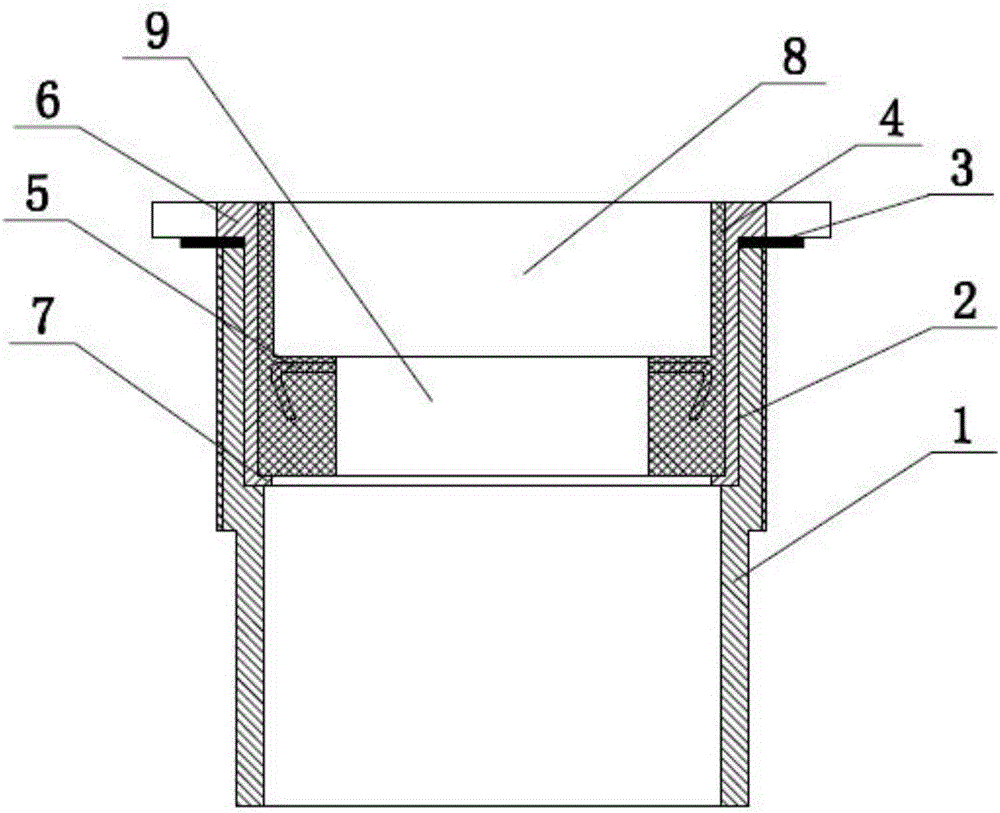
[0024] The invention provides a bobbin spindle connector, such as figure 1 As shown, i...


PUM


Abstract

The invention discloses a bobbin and spindle connector which comprises a shell, a sleeve, a yarn cutter and a positioning sleeve. A first clamping portion is arranged at the upper end of the sleeve, a second clamping portion is arranged at the lower end of the sleeve and fixed in the shell, the first clamping portion is clamped to the top end of the shell, and the yarn cutter is arranged between the top end of the shell and the first clamping portion and protrudes outwards; the positioning sleeve is arranged in the sleeve through the second clamping portion, an inner hole formed in the upper end of the positioning sleeve serves as a bobbin connection hole, and an inner hole formed in the lower end of the positioning sleeve serves as a spindle connection hole. By applying the bobbin and spindle connector, a bobbin and a spindle are connected, a traditional spindle structure can be remained, the spindle speed is guaranteed, and the advantages of being low in equipment cost and yarn breakage rate are achieved.

Description

technical field [0001] The invention relates to the technical field of spinning machine accessories, in particular to a bobbin spindle connector. Background technique [0002] The ring spinning frame is a kind of commonly used spinning equipment. The roving sliver spun by the roving frame in the previous process is further drafted and twisted into fine yarn, and wound on the yarn mounted on the spindle. On the tube, it is used in the subsequent process (winding); the bobbin and the spindle are connected in a certain form, so that when the spindle rotates at high speed, it will rotate with the bobbin, and at the same time complete the twisting and winding functions. [0003] With the advancement of technology, the spinning frame collective doffing system is often used in the yarn making process to reduce the cost of yarn making, reduce labor intensity and meet the application of advanced fine-bonding technology; while the traditional spinning frame bobbin and spindle In the ...

Claims


Application Information

Patent Timeline
Patent Type & Authority Applications(China)
IPC IPC(8): D01H7/16D01H9/16
CPCD01H7/16D01H9/16
Inventor 贠政端
Owner 晋中经纬恒腾纺机有限公司
Learn More