Filling method for unreinforced light soil abutment back

A light-weight soil and light-weight technology, applied in buildings, roads, roads, etc., can solve problems such as non-destructive testing, affecting the stability and durability of light-weight soil subgrades, voids, etc., to improve bearing capacity and stability, It is beneficial to detect the quality of the project and improve the effect of the strength of the roadbed

Active Publication Date: 2017-05-31
HOHAI UNIV
View PDF5 Cites 10 Cited by
  • Summary
  • Abstract
  • Description
  • Claims
  • Application Information

AI Technical Summary

Problems solved by technology

However, in practical applications, the thickness of each layer of filling with light soil filling is generally required to be less than 1 meter; the drainage of the light soil subgrade backfilled at the back of the abutment is often drained from the bottom of the PVC pipe, and the water infiltrated into the subgrade is difficult to discharge; Soil reinforcement mostly adopts horizontal steel bars or laying steel mesh, which is expensive, easy to rust, and the integrity is not strong. For example, when the load is applied, it is easy to produce voids; the influence of internal steel bars on reinforced light soil roads cannot be detected by radar. Non-destructive testing; due to the intrusion of rainwater, the bubble structure is destroyed, seriously affecting the stability and durability of the light soil subgrade, and at the same time, causing waste of water resources; and after the construction is completed, the light soil platform back subgrade is usually not further processed , the appearance of the concrete panel is exposed to people's vision, which affects the greening and beauty of the surrounding environment

Method used


Image

  • Filling method for unreinforced light soil abutment back
  • Filling method for unreinforced light soil abutment back
  • Filling method for unreinforced light soil abutment back

Examples


Embodiment

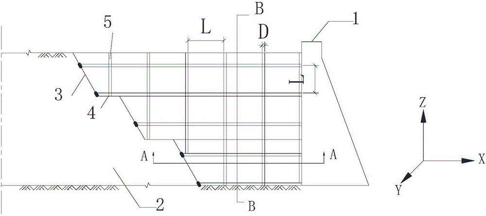
[0054] In this example, during the normal maintenance process, the inside of the PVC pipe is saturated sand, the width of the road bed is W, and the length of the roadbed at the back of the platform is L u , when the gutter is filled with water, the capacity V is

[0055] V=2WL u h u (1)

[0056] There are about n horizontal outlets of PVC pipes on both sides of the roadbed, and the cross-sectional area of ​​the outlets is

[0057] S=nπD 2 / 4 (2)

[0058] Gradually replenish the water stored in the slope protection vegetation soil through the saturated medium-coarse sand in the PVC pipe, and it takes about

[0059] t=V / kS (3)

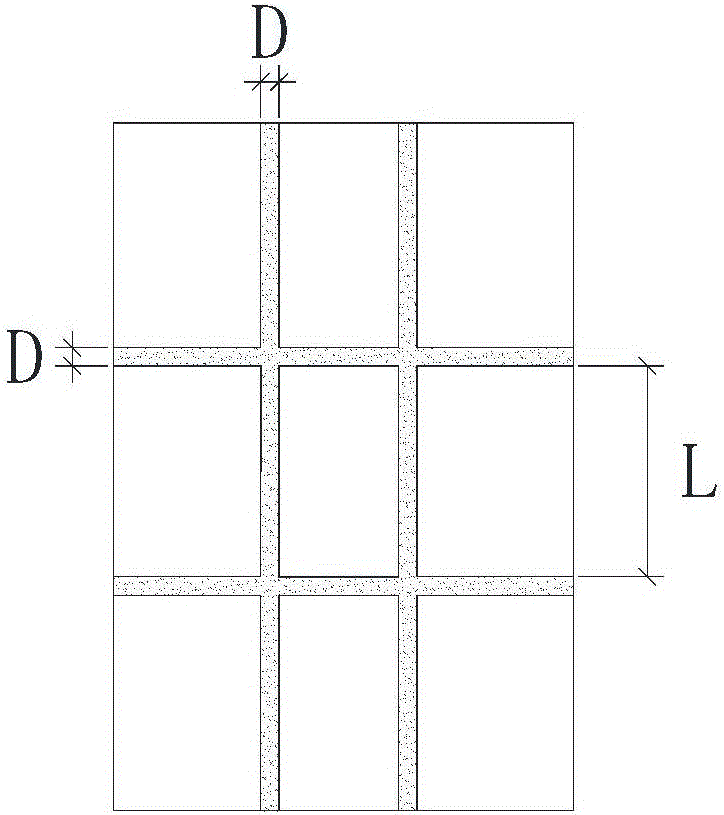
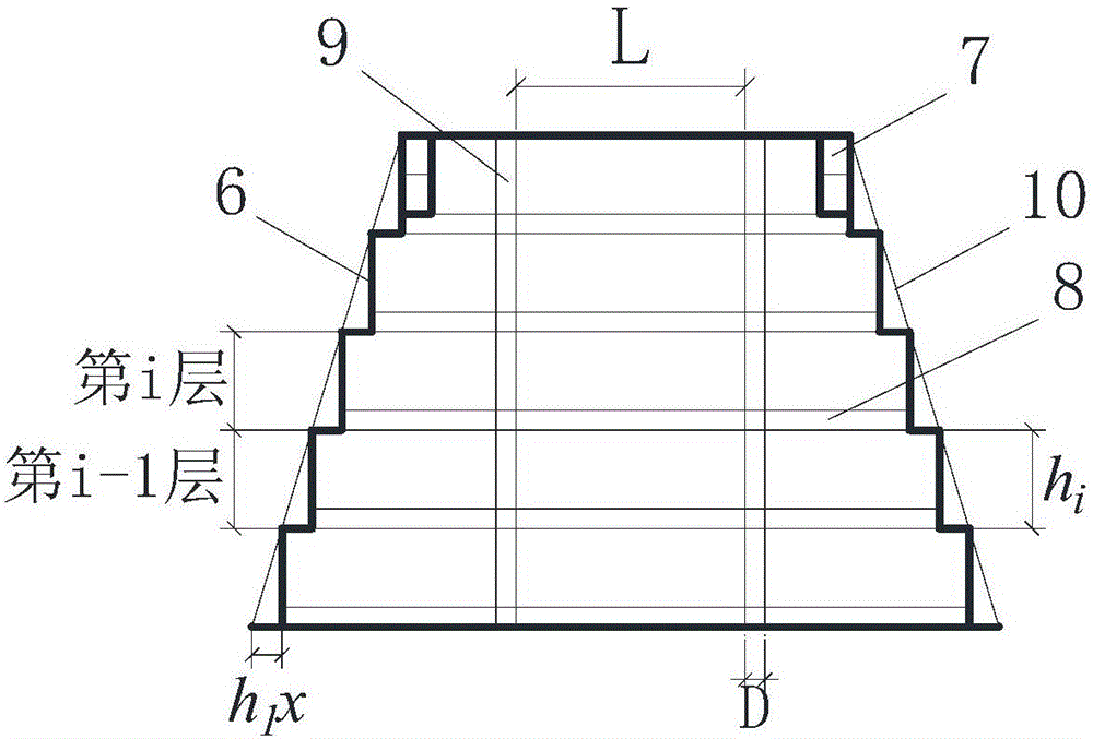
[0060] In this embodiment, the vertical and horizontal beams are arranged staggeredly in each layer, and there is a filling area in the middle. Each layer of light soil subgrade is simplified as a composite foundation, the vertical and horizontal beams are regarded as "cross piles", and the filled light soil is regarded as soil. Each layer The b...


PUM


Abstract

The invention discloses a filling method for an unreinforced light soil abutment back. Longitudinal beams and transverse beams on the first layer are formed block by block in a filled manner between the abutment back and a non-light-soil roadbed. Spaces formed by the longitudinal beams and the transverse beams on the first layer are filled with light soil adopted by a conventional light soil roadbed. After the first layer is filled, longitudinal beams and transverse beams on the second layer are filled in the manner that the longitudinal beams and the transverse beams on the second layer are staggered from the longitudinal beams and the transverse beams on the first layer, spaces formed by the longitudinal beams and the transverse beams on the second layer are filled with the light soil adopted by the conventional light soil roadbed, and filling construction is conducted in the same manner. Sand filling PVC pipes are arranged in the unreinforced light soil roadbed, so that the filling temperature stress is released, and the pipes serve as roadbed drainage channels. By the adoption of the filling method, the bearing capacity and stability of the high and large abutment back light soil roadbed are improved, meanwhile reinforced materials such as reinforcing meshes are prevented from being used in the filling process, the manufacturing cost is reduced, the integrity of the light soil roadbed is enhanced, and the engineering quality can be detected through radar and other non-destructive testing technologies in the later period.

Description

technical field [0001] The invention relates to the field of construction engineering, in particular to a method for filling an unreinforced lightweight soil platform back. Background technique [0002] With the rapid development of the national economy, from the city to the mountainous area, from the coast to the inland, highways, urban expressways and other transportation methods have been widely constructed, and the phenomenon of "jumping at the bridge head" seriously affects the safety and comfort of driving. has attracted much attention since. The problem of "jumping at the bridge head" is traditionally solved through the foundation treatment of the back of the abutment and strict backfilling of the back of the abutment. Not ideal. Lightweight soil has the advantages of small weight, high strength, and convenient construction. It can well solve the problems of land acquisition and demolition, shortage of soil sources, insufficient construction work area, and high proj...

Claims


Application Information

Patent Timeline
Patent Type & Authority Applications(China)
IPC IPC(8): E01C3/00E01C3/04
CPCE01C3/00E01C3/04
Inventor 刘鑫单浩赵四汉李之隆盛柯徐奋强洪宝宁
Owner HOHAI UNIV
Why Eureka
Try Eureka