Bottom bearing type folding truss bridge structure

A truss bridge and truss technology, applied in the directions of portable bridges, bridges, bridge parts, etc., can solve the problems of complex joints, poor rigidity, etc., and achieve the effect of overcoming numerous and messy rods, reasonable structure, and simple design and construction.

Active Publication Date: 2017-05-31
SOUTHEAST UNIV
View PDF10 Cites 2 Cited by
  • Summary
  • Abstract
  • Description
  • Claims
  • Application Information

AI Technical Summary

Problems solved by technology

However, it is rarely used in long-span structures due to the complexity of the nodes involved and poor stiffness.

Method used


Image

  • Bottom bearing type folding truss bridge structure
  • Bottom bearing type folding truss bridge structure
  • Bottom bearing type folding truss bridge structure

Examples


Embodiment Construction

[0019] Below with reference to accompanying drawing of description, the present invention is described in more detail:

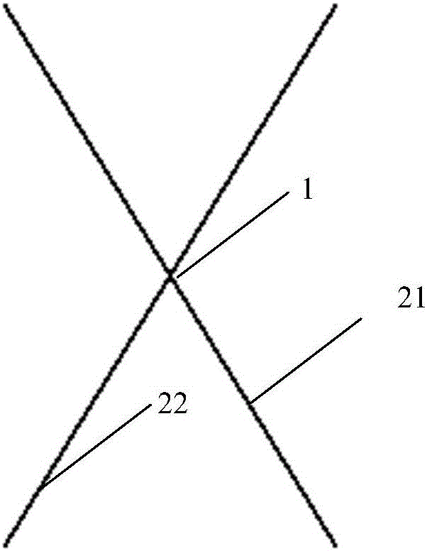
[0020] Scissor unit 1 in the structural span figure 1 As shown, a scissor unit is formed by pinning two straight rods 21 and 22 at the midpoint of the two rods. Such as figure 2 , the scissor units 1 are connected in the length direction of the structure to form a folded truss unit 4 .

[0021] When the structure is unfolded, the cables 3 are tightened, and the cables are arranged on the upper and lower edges of a folded truss unit 4. The folded truss of the cables is as follows: Figure 5 shown.

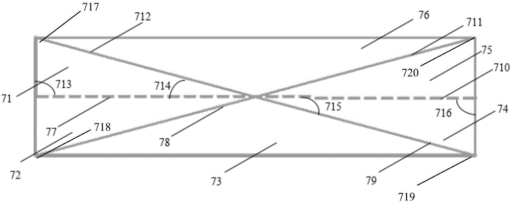
[0022] The rigid bridge deck 5 is composed of rigid bridge deck subunits 6 connected together. The rigid bridge deck subunits are arranged under the two folded truss units 4 . The rigid bridge deck subunit 6 is fully deployed as image 3 As shown, half-expanded as Figure 4 shown. Each rigid bridge deck subunit 6 is composed of six triangular plates 7 and...


PUM


Abstract

The invention discloses a bottom bearing type folding truss bridge structure. The bottom bearing type folding truss bridge structure is composed of a folding truss and a panel structure on the folding truss. The folding truss comprises two folding truss units, a beam connected between the two folding truss units, and inhaul cables used for folding and unfolding the folding truss units. Every two adjacent lower chord joints on one folding truss unit and two adjacent lower chord joints, at the corresponding positions, on the other folding truss units form a rectangular installation area. The panel structure is composed of rigid panel subunits in the rectangular installation areas. The bottom bearing type folding truss bridge structure has the advantages that no extra internal force is generated because the mechanisms are in kinematic compatibility in the folding and unfolding process, and thus the stress performance is excellent; besides, the folding dome mechanism is a single-degree-of-freedom system, and thus the number of driving devices is reduced; moreover, the bottom bearing type folding truss bridge structure is convenient to move and transfer, reusable, reasonable in construction, easy to design and construct and especially suitable for small-and-medium span bridges.

Description

technical field [0001] The invention relates to an under-supported folding truss structure, in particular to an under-supporting folding truss bridge structure. Background technique [0002] Since the Spanish architect Pinero first successfully applied the concept of expandable structure to the design of "movable theater" in the 1960s, the application of openable roofs in large-span spatial structures has increased rapidly. On the other hand, with the acceleration of people's exploration of outer space, deployable structures have received extensive attention, and relevant research results have been applied to space solar panels and satellite antennas. At present, the most widely used one is the expandable structure based on scissor like element. From a geometric point of view, the basic principle of this type of deployable structure is that each pair of connecting rods is connected by a column hinge, and each pair of connecting rods can only rotate relative to the axis perp...

Claims


Application Information

Patent Timeline
Patent Type & Authority Applications(China)
IPC IPC(8): E01D15/12E01D19/12
CPCE01D15/124E01D19/005E01D19/125
Inventor 蔡建国张骞王馨玉冯健
Owner SOUTHEAST UNIV
Why Eureka
Try Eureka