
Drainage valve noise reduction structure with overflow pipe

A technology of overflow pipe and drain valve, which is applied to flushing equipment with water tanks, water supply equipment, and sanitary equipment for toilets, etc., to achieve obvious noise reduction effects, ingenious ideas, and easy implementation

Pending Publication Date: 2017-05-31
XIAMEN R&T PLUMBING TECH
View PDF0 Cites 1 Cited by
  • Summary
  • Abstract
  • Description
  • Claims
  • Application Information

AI Technical Summary

Problems solved by technology

[0003] In order to solve the above problems, the present invention provides a drain valve noise reduction structure with an overflow pipe, which can form a water seal at the outlet of the overflow channel when the drain valve drains water, thereby preventing external air from being sucked into the overflow pipe. Drainage channel to improve the noise problem during the draining process of the drain valve

Method used


Image

  • Drainage valve noise reduction structure with overflow pipe
  • Drainage valve noise reduction structure with overflow pipe
  • Drainage valve noise reduction structure with overflow pipe

Examples


Embodiment Construction

[0030] In order to make the technical problems, technical solutions and beneficial effects to be solved by the present invention clearer and clearer, the present invention will be further described in detail below in conjunction with the accompanying drawings and embodiments. It should be understood that the specific embodiments described here are only used to explain the present invention, not to limit the present invention.

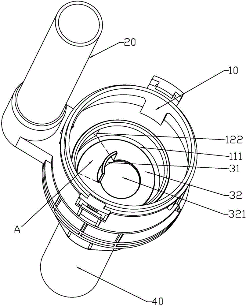
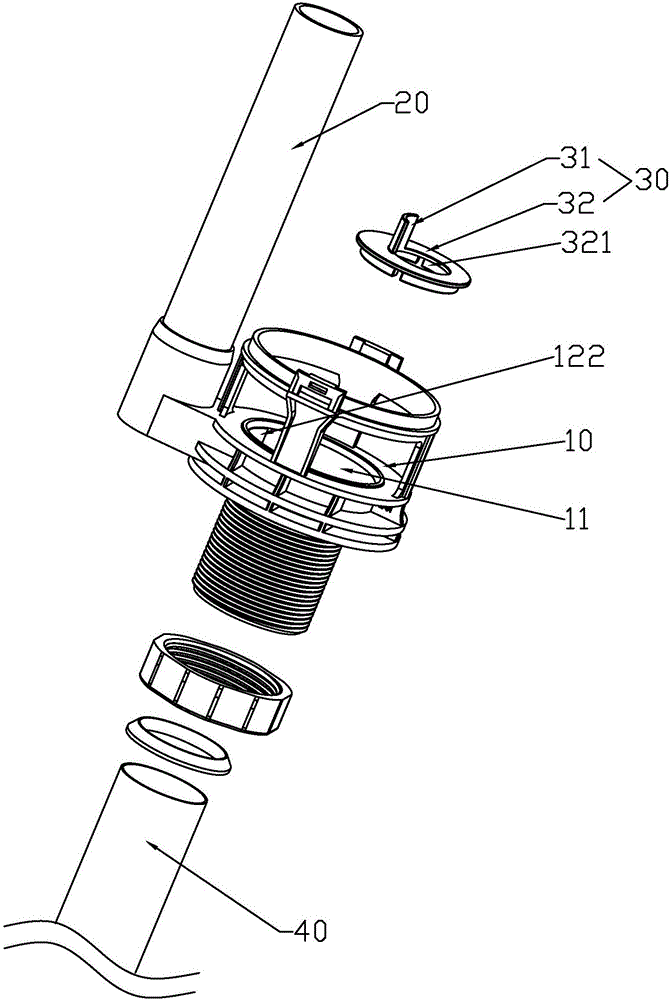
[0031] Such as Figure 2 to Figure 5 As shown, a drain valve noise reduction structure with an overflow pipe according to a specific embodiment of the present invention includes a base 10 and an overflow pipe 20 of the drain valve, the base is provided with a drain channel 11 and an overflow channel 12, and the base 10 The bottom end of the drainage channel 11 is connected with a vertical pipe 40, and the bottom end of the vertical pipe 40 is connected with the flushing inlet of the toilet (not shown in the figure), and the inlet 121 of the overflow cha...


PUM


Abstract

The invention discloses a drainage valve noise reduction structure with an overflow pipe. The drainage valve noise reduction structure comprises a base of a drainage valve and the overflow pipe, a drainage channel and an overflow channel are arranged in the base, the inlet of the overflow channel is communicated with the overflow pipe, the outlet of the overflow channel is communicated with the drainage channel, the overflow pipe is communicated with the drainage channel through the overflow channel in the base, a water blocking part is arranged in the drainage channel, and the water blocking part brings in part of water flow and blocks the same in the overflow channel when water is drained from the drainage channel to enable water seal to form in the outlet of the overflow channel. By the arrangement that the water blocking part is arranged in the drainage channel and brings in part of the water flow and blocks the same in the overflow channel when the water is drained from the drainage channel to enable the water seal to form in the outlet of the overflow channel, so that the problem that outside air is fed in the drainage channel of the drainage valve from the overflow pipe to produce continuous noise is effectively avoided; the drainage valve noise reduction structure is simple in structure, ingenuous in concept and obvious in noise reduction effect.

Description

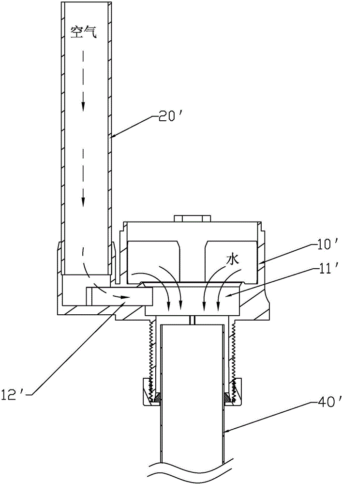
technical field [0001] The invention relates to a noise reduction structure of a drain valve with an overflow pipe. Background technique [0002] Among the many toilet flushing devices, there is one that uses the drop-flush type for drainage. The drop-flush type toilet flushing device generally uses a water tank located at a high level. Potential energy water can be drained down quickly, so as to improve the flushing force of the toilet and make the cleaning effect good. The high-level water tank is relatively high due to the position of the water tank, such as figure 1 As shown, the water flow tends to form a full pipe in the vertical pipe 40' between the base 10' of the drain valve and the toilet, thereby forming a siphon phenomenon, which will cause the water flow to form a strong suction force at the drain outlet of the drain valve in the water tank , and the existing drain valve base 10' mostly has an overflow pipe 20', and the overflow pipe 20' is generally set to pa...

Claims


Application Information

Patent Timeline
IPC IPC(8): E03D9/14E03D1/34
CPCE03D1/34E03D9/14Y02A30/60
Inventor 江力郑江辉洪其城张荣誉
Owner XIAMEN R&T PLUMBING TECH
Learn More