
Three-dimensional seismic isolation device
A seismic isolation, three-dimensional technology, applied in the direction of earthquake resistance, building types, buildings, etc., can solve the problems of superstructure offset, no correction measures, and seismic isolation equipment have not yet been used, etc., to achieve the effect of reducing damage
- Summary
- Abstract
- Description
- Claims
- Application Information
AI Technical Summary
Problems solved by technology
Method used
Image

Examples
Embodiment 1
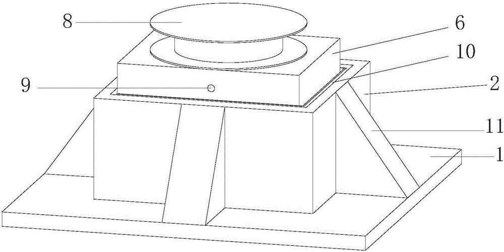
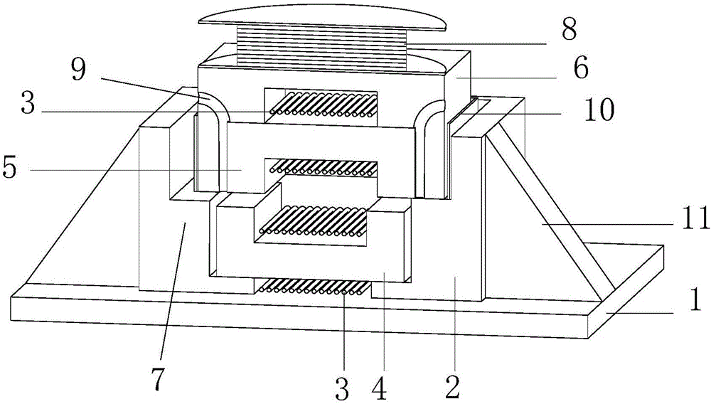
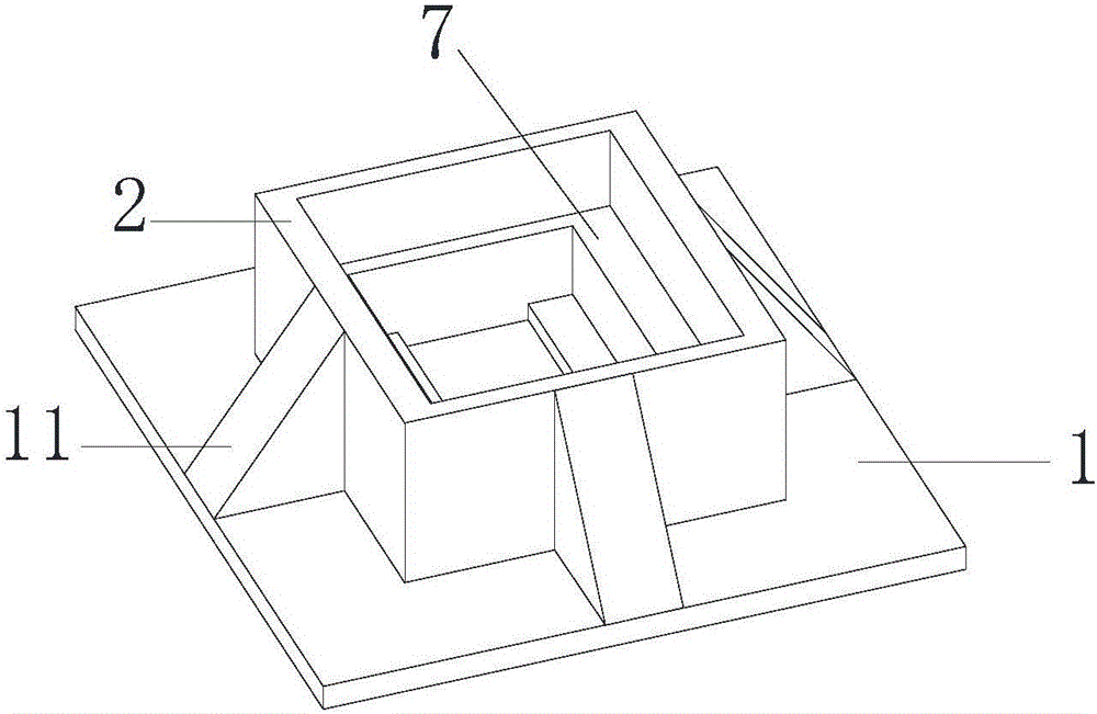
[0026] Please refer to the attached figure 1 , 2 , a three-dimensional seismic isolation device provided by the present invention is fixedly connected to a structural chassis 1 and includes a cylindrical base 2 fixed on the structural chassis 1 . The bottom of the base 2 is provided with a mounting position for the first iron core 4 wound with the coil 3 , and the first iron core 4 is fixed on the bottom of the base 2 by welding or bonding. A limiting step 7 is also provided on the inner side wall of the base 2 for installing a positioning frame 6 . The positioning frame 6 is used to fix the second iron core 5 around which the coil 3 is wound. The bottom surface of the positioning frame 6 is open and has a mounting position for the second iron core 5 inside. Let the positioning frame 6 rest on the preset limit step 7 of the base 2 with the opening facing down, and buckle it upside down on the second iron core 5, that is, the positioning frame 6 is fastened to the second iron...
Embodiment 2
[0037] Please refer to the attached Image 6 , The difference between this embodiment and Embodiment 1 is that the horizontal vibration-isolation support 8 in this embodiment adopts a friction pendulum vibration-isolation support. The friction pendulum shock-isolation support in this embodiment belongs to the prior art shock-isolation support, and its internal structure and functions will not be described in detail here. In other embodiments of the present invention, the horizontal shock-isolating support 8 may be an elastic slide plate shock-isolating support or other shock-isolating supports with the same or similar functions.
PUM
 Abstract
Description
Claims
Application Information