Multi-interface transverse pull rod, simple transverse pull rod, slant bracing rod and tower frame

A tie rod and multi-interface technology, which is applied in the field of simple tie rods, diagonal braces and towers, and multi-interface tie rods, can solve the problems that the tie rods cannot provide connection parts, the stability of the support system is damaged, and the number of fasteners is large. , to achieve the effects of eliminating stability factors, reducing erection costs, and facilitating processing

Inactive Publication Date: 2017-05-31
泰博新型建筑科技(苏州)有限公司
View PDF6 Cites 1 Cited by
  • Summary
  • Abstract
  • Description
  • Claims
  • Application Information

AI Technical Summary

Problems solved by technology

However, the force of the wedging or withdrawal process of the existing oblique wedge locking is horizontal, and away from the vertical bearing surface formed between the center of the riser and two adjacent standpipes, which has a great impact on the stability of the support system. destructive effect, there is a greater security risk
In addition, the original fasteners usually can only connect one end of the tie rod or diagonal brace to the standpipe, and cannot provide connecting parts for other adjacent tie rods. When the system is erected, the number of fasteners is large and the erection cost is high

Method used


Image

  • Multi-interface transverse pull rod, simple transverse pull rod, slant bracing rod and tower frame
  • Multi-interface transverse pull rod, simple transverse pull rod, slant bracing rod and tower frame
  • Multi-interface transverse pull rod, simple transverse pull rod, slant bracing rod and tower frame

Examples


Embodiment 1

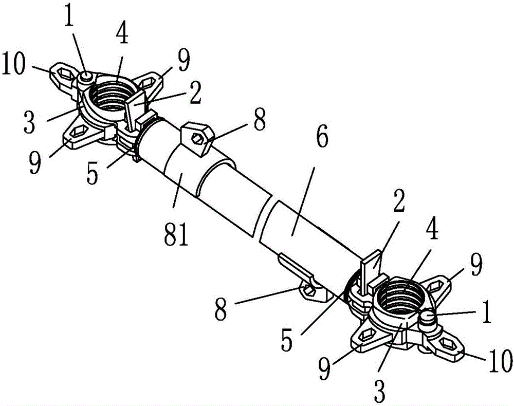
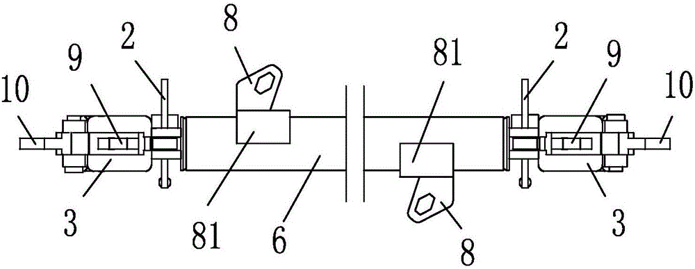
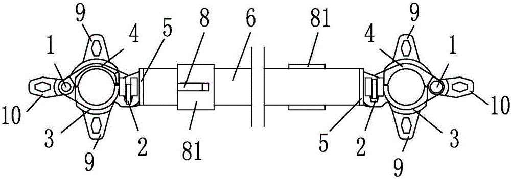
[0040] Example 1, see Figure 1-7 , a multi-interface tie rod, including a tubular tie rod main body 6, the two distal ends of the tubular tie rod main body 6 are fixedly connected with fasteners, and the fasteners include a first semicircular clip hinged by a pin shaft 1 and locked by a wedge 2 The hoop 3 and the second semicircular hoop 4, while the plane passing through the hoop and the axis of the pin shaft 1 constitutes the symmetry plane of the fastener, and the locking or unlocking direction of the wedge 2 is parallel to the symmetry plane; The domes of the semicircle clamp 3 and the second semicircle clamp 4 are provided with a first expansion interface 9, the first expansion interface 9 has a wedge locking structure with a third member, and the first expansion interface 9 is provided with The direction of the first expansion locking hole 9a is parallel to the plane of symmetry; the first semicircular clamp 3 is also provided with a second expansion interface 10; 10 h...

Embodiment 2

[0045] Example 2, see Figure 8 , 9 , 10, a simple horizontal tie rod, comprising a tubular tie rod main body 6 and tie rod joints 12 arranged at both ends of the tubular tie rod main body 6 by welding, a brace interface 8 and a brace interface are respectively provided on the pipe walls at both ends of the tubular tie rod main body 6 8 has a wedge-locked structure with another third component, and the two brace interfaces 8 have a phase difference of 180 degrees; the tie rod joint 12 has a U-shaped fork structure to be connected to the first expansion interface 9 in Embodiment 1, or The plug-type connection ear of the second expansion interface 10 forms a connection structure of plug-in fit, and the rod joint 12 is formed with a strip-shaped joint locking hole 12a for wedge locking, and the length direction of the joint locking hole 12a is in line with the described The axial directions of the tubular tie rod main body 6 are consistent.

[0046] Wherein, the brace interface...

Embodiment 3

[0048] Example 3, see Figure 11 , 12, 13. A diagonal brace, comprising a diagonal brace main body 13, two ends of the diagonal brace main body 13 are provided with a tie rod joint 12, and the tie rod joint 12 has a U-shaped fork structure, which is used for connecting with the diagonal brace in Embodiment 1 or 2. The plug-type connecting ear of the interface 8 forms a connection structure of plug-in fit, and the rod joint 12 is formed with an elongated joint locking hole 12a for wedge locking. The length direction of the joint locking hole 12a is in line with the diagonal brace The axes of the main body 13 are consistent.

[0049] Apparently, the tie rod joint 12 in this embodiment may also have a connection structure of a plug-in type connection ear, which has formed a connection structure of plug-fitting with the brace interface 8 of the U-shaped fork structure.


PUM


Abstract

The invention discloses a multi-interface transverse pull rod, a simple transverse pull rod, a slant bracing rod and a tower frame. The multi-interface transverse pull rod comprises a tubular pull rod body and wedge-shaped locking fasteners at the two ends of the body, and each fastener is provided with a first expanding interface; slant bracing interfaces are arranged on the pipe walls of the two ends of the tubular pull rod body respectively, and the two slant bracing interfaces are staggered at 180 degrees; the simple transverse pull body comprises a tubular pull rod body and pull rod connectors at the two ends of the tubular pull rod body, and the pull rod connectors and the first expanding interfaces in the multi-interface transverse pull rod form a slant wedge locking structure; the pipe walls of the two ends of the tubular pull rod body are provided with slant bracing interfaces respectively; the slant bracing rod comprises a slant bracing rod body and pull rod connectors arranged at the two ends of the slant bracing rod body, the pull rod connectors and the slant bracing interfaces in the multi-interface transverse pull rod or the simple transverse pull body form a slant wedge locking match; the tower frame is formed by erecting a stand pipe, the multi-interface transverse pull rod, the simple transverse pull rod and the slant bracing rod. The multi-interface transverse pull rod, the simple transverse pull rod, the slant bracing rod and the tower frame have the advantages that slant wedge locking structures are all adopted in the fasteners and the expanding interfaces, the tower frame is convenient to put up and dismantle and firm in locking, the quantity of the fasteners is small, and the efficiency in putting up and dismantling is high.

Description

technical field [0001] The invention relates to building construction scaffolding or formwork support system building components, in particular to a multi-interface tie rod, a simple tie rod, a diagonal brace and a tower. Background technique [0002] During the building construction process, it is necessary to set up scaffolding and formwork support systems. In order to meet the requirements of modern construction, the scaffolding or supporting system not only needs to have sufficient safety guarantee, but also requires higher and higher erection efficiency. At present, there are two commonly used erection methods, one is erected through grid frames, and the other is erected through standpipes plus horizontal pipes or diagonal bracing pipes. The installation of the net frame requires a height-adjustable bowl seat under the net frame, and the net frame is large in size, and the transportation of the net frame is extremely inconvenient, the transportation cost is high, and t...

Claims


Application Information

Patent Timeline
Patent Type & Authority Applications(China)
IPC IPC(8): E04G5/16E04G1/06
CPCE04G1/06E04G5/16
Inventor 张健华孟先华
Owner 泰博新型建筑科技(苏州)有限公司
Why Eureka
Try Eureka