

Telescopic mobile chute tube
A mobile, sliding drum technology, applied in the field of concrete pouring, can solve the problems of low pouring efficiency, high labor intensity of workers, waste of concrete, etc.
Active Publication Date: 2017-05-31
平邑经发科技服务有限公司
View PDF9 Cites 4 Cited by
- Summary
- Abstract
- Description
- Claims
- Application Information
AI Technical Summary
Problems solved by technology
[0002] At present, when pouring concrete on the ground or on the road in the field of construction engineering, the concrete is poured directly to the ground by the concrete tank truck, and the workers then use the target to pick up the concrete to the pouring point. Raking the rake to a distance not only reduces the efficiency of pouring, but also increases the labor intensity of the workers and wastes concrete
Method used
View moreImage
Smart ImageViewing Examples

Examples
Embodiment Construction
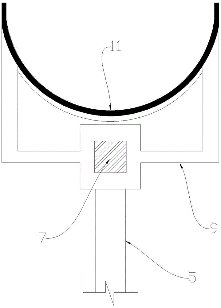
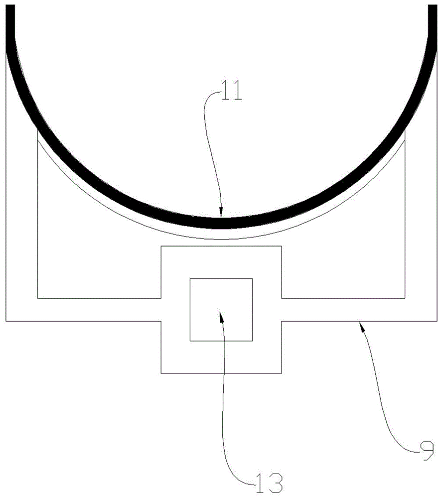
[0010] Summary of the Invention The specific implementation of the present invention has been described in detail, and will not be repeated here; it should be noted that the shaft section of the telescopic rod 7 matches the hole 13, and the shaft section of the telescopic rod 7 is either square or oval. Or any other shape except the circle, because if the shaft section of the telescopic rod 7 is circular, the hole 13 of the movable frame 9 can rotate around the telescopic rod 7 .
Login to View More PUM
 Abstract
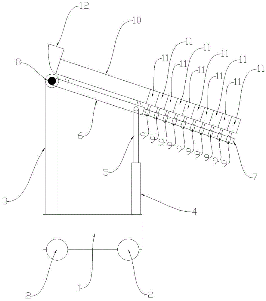
The invention provides a telescopic mobile chute tube which is mainly used for concrete pouring in the field of constructional engineering and is high in pouring efficiency and capable of saving concrete and reliving the labor intensity of workers. The telescopic mobile chute tube is mainly composed of a vehicle frame, wheels, a stand rack, a hydraulic cylinder, a hydraulic piston, a telescopic rod, mobile racks, a fixed chute tube body, a plurality of mobile chute bodies and a feed hopper. According to the main working principle of the telescopic mobile chute tube, concrete slides over the fixed chute tube body and the mobile chute bodies from top to bottom, slides out of the mobile chute tube body at the foremost end and enters a pouring point; if the concrete needs to be poured to a place far away, the telescopic rod is rightwards stretched, the front end of the telescopic rod drives the mobile chute tube body at the foremost end to forwards move, and when a limiting ring of the mobile chute tube body at the foremost end makes contact with a limiting ring of the second section of mobile chute tube body, the second section of mobile chute drum body is pulled out, and in the same way, the other sections of mobile chute tube bodies are pulled out; and the inclination angle and the height of concrete discharging can be changed by stretching and retracting the hydraulic piston.
Description
technical field [0001] The invention is mainly used for pouring concrete in the field of construction engineering. Background technique [0002] At present, when pouring concrete on the ground or on the road in the field of construction engineering, the concrete is poured directly to the ground by the concrete tank truck, and the workers then use the target to pick up the concrete to the pouring point. If the rakes are pulled far away, not only the pouring efficiency is low, the labor intensity of the workers is high, and the concrete is wasted. Contents of the invention [0003] The present invention solves the above problems. It not only has high pouring efficiency, saves concrete, but also reduces the labor intensity of workers; , hydraulic piston (5), arm (6), telescopic rod (7), shaft (8), movable frame (9), fixed chute (10), movable chute (11), and feed hopper (12) The vehicle frame (1) is equipped with multiple wheels (2), the vehicle frame (1) can move horizontal...
Claims
Login to View More Application Information
Patent Timeline
 IPC IPC(8): E04G21/04E01C19/18
CPCE01C19/182E04G21/0481
Inventor彭宝安
Owner平邑经发科技服务有限公司