Axial-moving multi-mode level type variable valve driving system

A drive system, mobile technology, applied in the direction of engine components, machine/engine, valve control, etc., to achieve the effect of good variable valve flexibility, high cost performance, and optimized operating conditions

Inactive Publication Date: 2017-05-31
DALIAN UNIV OF TECH
View PDF7 Cites 3 Cited by
  • Summary
  • Abstract
  • Description
  • Claims
  • Application Information

AI Technical Summary

Problems solved by technology

At present, there is no variable valve drive system that can meet the above requirements at the same time, so the development of a multi-mode variable valve drive system is imminent

Method used


Image

  • Axial-moving multi-mode level type variable valve driving system
  • Axial-moving multi-mode level type variable valve driving system
  • Axial-moving multi-mode level type variable valve driving system

Examples


Embodiment Construction

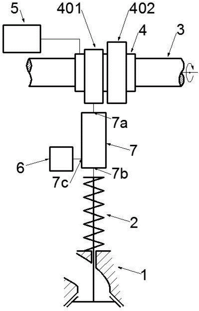
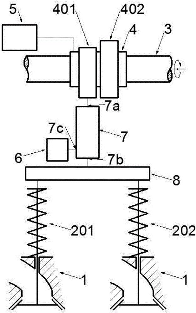
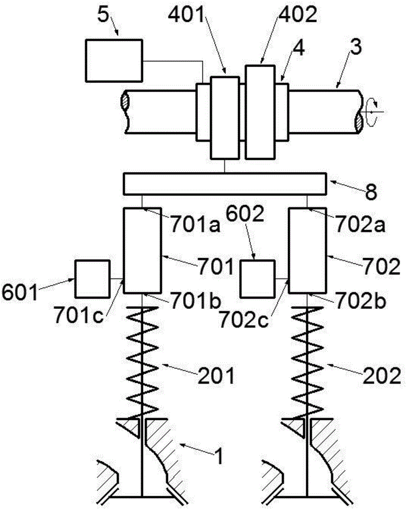
[0038] The invention relates to an axially movable multi-mode lever variable valve drive system. It includes a valve driving mechanism 2, a camshaft 3, a camshaft sleeve 4, an axial movement mechanism 5, a valve control mechanism 6, and a valve adjustment lever 7. figure 1 It is a schematic diagram of an axially moving multi-mode lever variable valve drive system driven by double cams and operated by a single valve. A first cam 401 and a second cam 402 are arranged on the camshaft sleeve 4 . The first cam 401 adopts a single-lobed cam blade or a double-lobed cam blade, the second cam 402 adopts a single-lobed cam blade or a double-lobed cam blade, and the double-lobed cam blades adopt camshafts with the same profile and a phase difference of 180° Two protrusions at the corners. The valve adjustment lever 7 has a valve adjustment lever input end 7a, a valve adjustment lever output end 7b and a valve adjustment lever adjustment end 7c. The axial movement mechanism 5 adjusts t...


PUM


Abstract

The invention belongs to the field of engine valve driving and discloses an axial-moving multi-mode level type variable valve driving system. The system mainly comprises a cam shaft, a cam shaft sleeve, an axial moving mechanism, a valve adjusting level, a valve control mechanism and the like. At least a first cam and a second cam are arranged on the cam shaft sleeve. By adoption of the axial moving mechanism, shifting among various mode including a two-stroke driving mode, a four-stroke driving module, a two-stroke braking mode, a four-stroke braking mode and the like of an engine is realized, and further, by joint use with the valve control mechanism, optimal aeration of the engine under different working conditions is finally realized, and comprehensive improvement of engine dynamic properties, fuel economy, emission performance and braking safety is realized. The system is provided aiming at practical application and is high in reliability and compact in structure, and requirements of the system on each mechanism are reduced; due to adoption of mature technologies for each mechanism, the system is high in short-term practical potential and has a promising application prospect.

Description

technical field [0001] The invention relates to an axially movable multi-mode lever variable valve driving system, which belongs to the field of engine valve driving. Background technique [0002] With the increasingly serious energy and environmental issues, and people's focus on driving and safety of vehicles, future engines need to comprehensively consider power, economy, emissions and safety on the premise of meeting emission standards. This requires optimizing engine performance over the full range of driving and braking conditions. At present, technologies such as variable valve, variable stroke number, cylinder deactivation, auxiliary braking, new combustion mode, variable compression ratio, variable EGR and other technologies that have attracted much attention only affect the performance of the engine in a small range of operating conditions. Make improvements. For example, the existing variable valve technology is only applied to the driving condition of the fixed...

Claims


Application Information

Patent Timeline
Patent Type & Authority Applications(China)
IPC IPC(8): F01L13/06F01L13/00F01L1/344
CPCF01L1/34413F01L13/00F01L13/0036F01L13/06F01L2710/003F01L2760/00
Inventor 崔靖晨隆武强田华杜宝国王阳刘威杨添淏
Owner DALIAN UNIV OF TECH
Why Eureka
Try Eureka