Intelligent air treatment device

An air handling device, an intelligent technology, applied in the direction of pump devices, air heaters, components of pumping devices for elastic fluids, etc., can solve the problems of uneven wind, reduced work efficiency, high blade speed, and achieve distraction , The effect of reducing work efficiency and reducing noise

Inactive Publication Date: 2017-05-31
卢碧莲
View PDF16 Cites 2 Cited by
  • Summary
  • Abstract
  • Description
  • Claims
  • Application Information

AI Technical Summary

Problems solved by technology

[0004] In the hot summer, the fan is an indispensable daily necessities in every family. It is said that the existing fan drives the blades to rotate through the motor, pressurizes the air through the blades and then blows it to the user. The advantage is to bring the user the feeling of blowing. However, there are four disadvantages as follows: first, the rotating blades have a high speed, and accidental contact will cause injury, so most fans use outer covers to surround the blades to reduce danger; second, it is difficult to clean the blades and outer covers; third, There will be noise during the rotation of the blades, which will disturb the users; Fourth, due to changes in the airflow passing through the surface of the blades, the wind blown out is not uniform, and the user will feel bursts of strong wind similar to pulses.
[0006] Bladeless fans are becoming more and more widely used, and there are more and more problems, especially because the bladeless fan adopts worm gear ventilation, its vibration is relatively large, and the noise problem is relatively immediate, which brings problems to consumers such as causing troubles, reducing work efficiency, Effects such as distraction and sleep disturbance to cause extreme distress

Method used


Image

  • Intelligent air treatment device
  • Intelligent air treatment device
  • Intelligent air treatment device

Examples


Embodiment Construction

[0036] The present invention will be further described below in conjunction with specific embodiments and accompanying drawings.

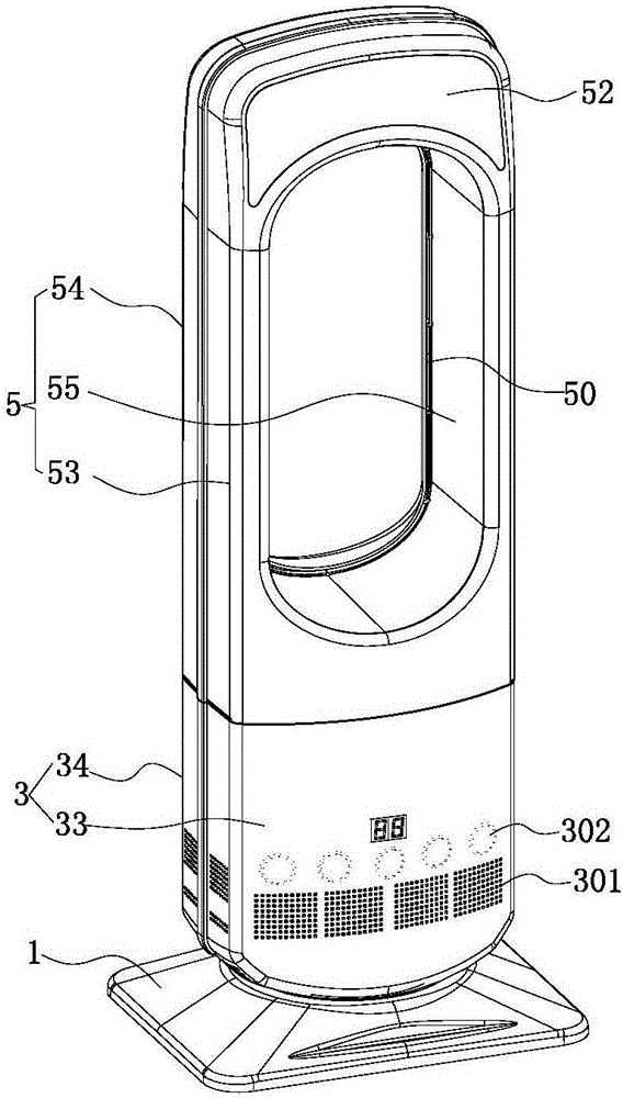
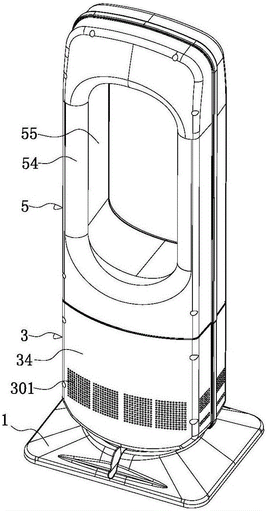
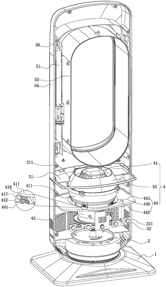
[0037] See Figure 1-7 As shown, it is an intelligent air treatment device, which is a bladeless fan, which includes: a base 1, a lower assembly installed on the base 1, and an upper assembly installed on the lower assembly.

[0038] The lower assembly includes: a lower housing 3 installed on the base 1 in a manner capable of shaking the head and tilting forward and backward through the swinging and reclining device 2 , and a turbine air outlet device 4 installed in the lower housing 3 . The lower casing 3 is provided with a partition 31 , and the partition 31 is provided with a hole 311 , and the upper end of the turbine air outlet device 4 passes through the hole 311 and is exposed outside the upper surface of the partition 31 .

[0039] The swing and tilt device 2 includes a swing and tilt fixed seat 21 installed on the base 1, a swing and tilt...


PUM


Abstract

The invention discloses an intelligent air treatment device which comprises a base, a lower part component and an upper part component; the lower part component is composed of a lower part shell installed on the base through a swing tipping device in a head shaking and leaning forward and backward manner and a turbine air outlet device installed in the lower part shell; air inlet holes are formed in the bottom and the outer side of the lower part shell; the turbine air outlet device is composed of a turbine mechanism, an air collection ring and an air outlet circle; the turbine mechanism is installed in the lower part shell through a shock absorption mechanism; the shock absorption mechanism is composed of a shock absorption bracket and shock absorption springs installed at mounting holes formed in the shock absorption bracket; the turbine mechanism is installed in the mounting holes of the shock absorption bracket; the shock absorption springs form elastic support to the turbine mechanism to enable the periphery of the turbine mechanism to form an interval with the inner walls of the mounting holes; a partition plate is arranged in the lower part shell and is internally provided with a hole position; the upper end of the air outlet device penetrates through the hole position and is exposed outside the upper end surface of the partition plate; the upper part component is composed of an upper part annular shell installed on the lower part component; the upper part annular shell is provided with an air outlet passage.

Description

[0001] Technical field: [0002] The invention relates to the technical field of household appliances, in particular to an intelligent air treatment device. [0003] Background technique: [0004] In the hot summer, the fan is an indispensable daily necessities in every family. It is said that the existing fan drives the blades to rotate through the motor, pressurizes the air through the blades and then blows it to the user. The advantage is to bring the user the feeling of blowing. However, there are four disadvantages as follows: first, the rotating blades have a high speed, and accidental contact will cause injury, so most fans use outer covers to surround the blades to reduce danger; second, it is difficult to clean the blades and outer covers; third, Also can produce noise in the blade rotation process, brings disturbance to the user; Fourth, because the air-flow changes when passing through the blade surface, the wind that blows out is not uniform, and the user can feel t...

Claims


Application Information

Patent Timeline
Patent Type & Authority Applications(China)
IPC IPC(8): F04D25/10F04D29/66A61L9/22F24H3/04
CPCA61L9/22F04D25/10F04D29/668F24H3/04F04F5/16
Inventor 卢碧莲
Owner 卢碧莲
Why Eureka
Try Eureka