
Synchronizers and Gearboxes

A technology for synchronizers and gearboxes, applied to clutches, mechanical drive clutches, components with teeth, etc., can solve problems that affect driving safety, wrong gears, and the outer ring cannot decelerate, etc.

Active Publication Date: 2019-06-25
ZHEJIANG WANGLIYANG TRANMISSION CO LTD
View PDF6 Cites 0 Cited by
  • Summary
  • Abstract
  • Description
  • Claims
  • Application Information

AI Technical Summary

Problems solved by technology

[0002] At present, the three-piece set of the synchronizer is the necessary original for the gear shifting of the double-cone and above synchronizer, but it is easy to appear that the contact surface between the middle ring of the three-piece set and the inner and outer rings is firmly adsorbed and cannot be disengaged during the shifting process. In this case, the outer ring cannot be decelerated, and other gears cannot be shifted, or the wrong gear may occur, and when the middle ring cannot be separated from the inner and outer rings, the meshing conical surfaces are prone to serious consequences of burning and burning. affect driving safety

Method used


Image

  • Synchronizers and Gearboxes
  • Synchronizers and Gearboxes

Examples


Embodiment

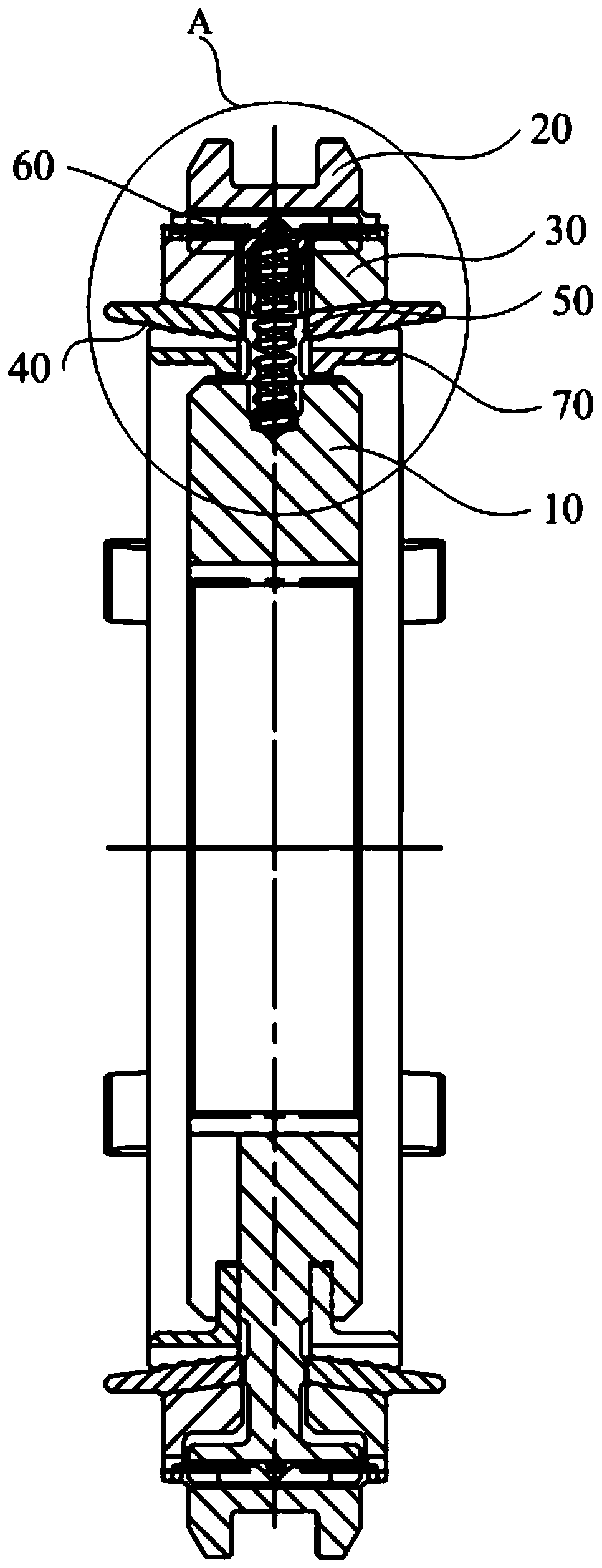
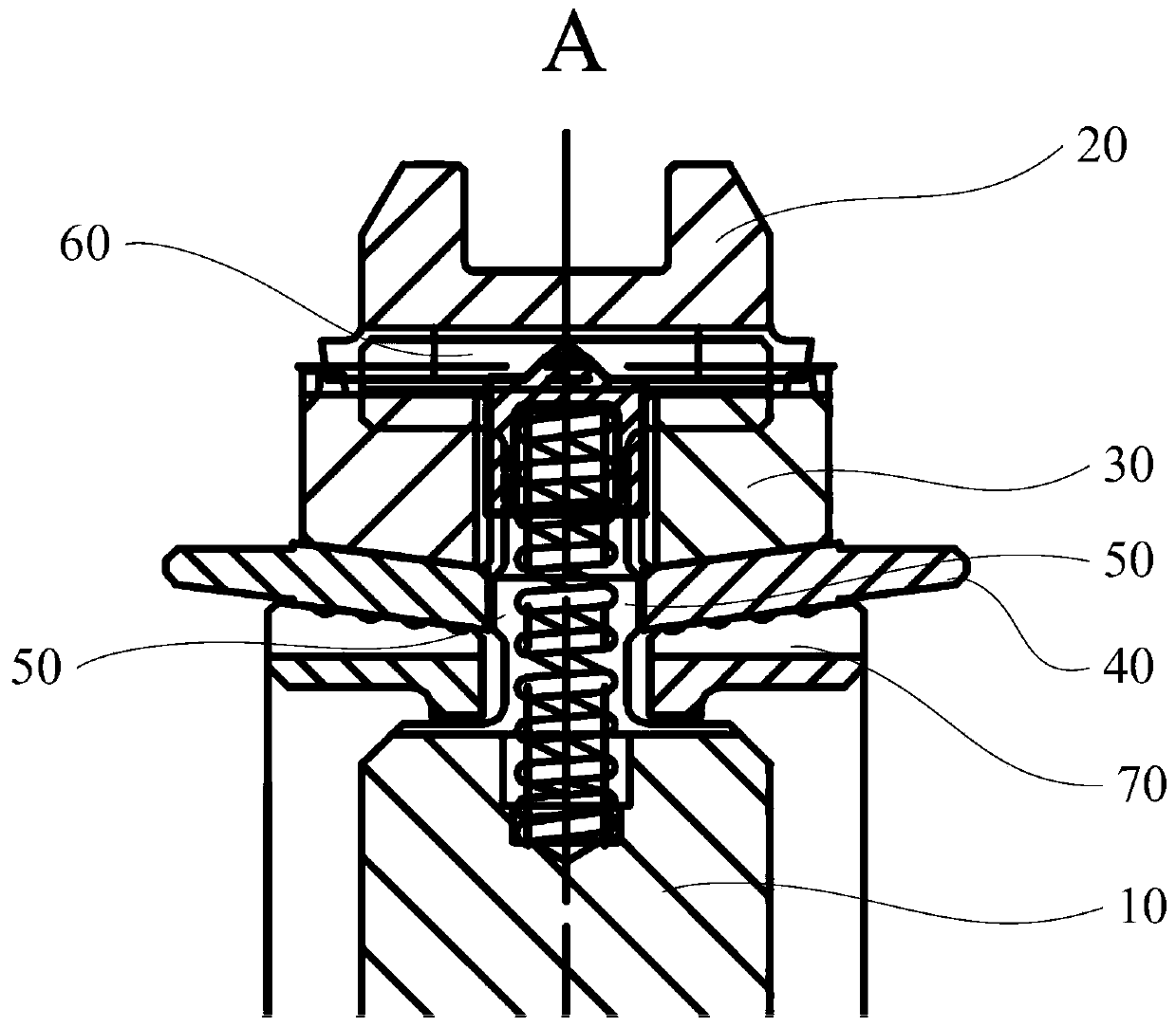
[0061] When it is necessary to shift gears from the right gear to the left gear: before gear shifting is started, the synchronizer gear sleeve 20 is located on the right side, and the middle ring 40 on the right side has a combination tooth matched with it at this moment. Speed, the middle ring 40 on the right transmits the speed to the outer ring 30 and inner ring 70 on the right through the tapered surface, and drives the gear hub 10 to have the same speed as the right coupling teeth; When the left gear is in gear, the synchronizer gear sleeve 20 starts to move from right to left, and the synchronizer gear sleeve 20 drives the lower outer ring 30 to move through the slider 60, and the outer ring 30 drives the middle ring in turn through friction. 40 and inner ring 70 move from right to left, at this moment, because the width of middle ring 40 is longer, the part protruding on it does not disengage from engaging tooth, so three-piece set (inner ring 70, middle ring 40 and oute...


PUM


Abstract

The invention provides a synchronizer and a gearbox. The radial outer wall of a gear hub is provided with a boss extending to the direction of a middle ring. When the gearbox needs gear shift and a synchronizer gear sleeve drives an outer ring and the middle ring to move leftwards or rightwards to the neutral gear position, the boss limits continued motion of the middle ring to the direction of the gear hub, the outer ring can continue to move toward the direction of the gear hub, at the moment, a vacuum adsorption face appearing due to synchronous rotation between the middle ring and the outer ring is damaged, and the outer ring does not have rotation speed of a combined gear connected with the middle ring any longer after leaving the middle ring. Therefore, the outer ring drives the synchronizer gear sleeve and the gear hub to decrease speed together, after the rotation speed is decreased, gear engaging to another combined gear can be easy, large rotation speed difference appearing when the gear hub is connected to another combined gear directly when still having the rotation speed of the former combined gear is avoided, thus the conditions of difficult gear engaging or wrong gear are avoided, and driving safety is ensured.

Description

technical field [0001] The invention relates to the field of automobile manufacturing, and more specifically, to a synchronizer and a gearbox. Background technique [0002] At present, the three-piece set of the synchronizer is the necessary original for the gear shifting of the double-cone and above synchronizer, but it is easy to appear that the contact surface between the middle ring of the three-piece set and the inner and outer rings is firmly adsorbed and cannot be disengaged during the shifting process. In this case, the outer ring cannot be decelerated, and other gears cannot be shifted, or the wrong gear may occur, and when the middle ring cannot be separated from the inner and outer rings, the meshing conical surfaces are prone to serious consequences of burning and burning. And then affect driving safety. [0003] Therefore, it is a problem to be solved urgently to design a synchronizer and a gearbox that have a simple structure and can separate the intermediate ...

Claims


Application Information

Patent Timeline
Patent Type & Authority Patents(China)
IPC IPC(8): F16D23/02F16H61/04
CPCF16D23/025F16H61/0403
Inventor 吴江徐卫权陈红芳
Owner ZHEJIANG WANGLIYANG TRANMISSION CO LTD
Learn More