Method for slowly releasing shock in two directions

A technology of one-way valve and outer cylinder, which is applied in the direction of shock absorber, spring, spring/shock absorber, etc., can solve the problems such as unable to provide return force, achieve stable and reliable working process, realize equalization, and realize two end-back effect

Inactive Publication Date: 2017-05-31
巴南区伟鹏机械加工厂
View PDF0 Cites 5 Cited by
  • Summary
  • Abstract
  • Description
  • Claims
  • Application Information

AI Technical Summary

Problems solved by technology

The return of the shock absorber is realized by the expansion of the compressed gas, and its return direction is one-way, which cannot provide a stable and average return force

Method used


Image

  • Method for slowly releasing shock in two directions

Examples


Embodiment 1

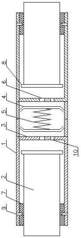
[0030] Such as figure 1 As shown, the two-way shock release method utilizes the equipment described below:

[0031] The device includes an outer cylinder 1, a compression column 2, a damping plate 3, a floating piston 4 and a spring 5; the outer cylinder 1 is arranged horizontally, both ends of the outer cylinder 1 are open, and two damping plates 3 are symmetrically arranged on the outer cylinder In 1, two floating pistons 4 are relatively arranged between two damping plates 3, and the two floating pistons 4 are connected by a spring 5; two compression columns 2 are respectively inserted into the outer cylinder 1 through both ends of the outer cylinder 1; The damping plate 3 is provided with a damping hole 6; the damping plate 3 is provided with a one-way valve 10 leading to the end of the outer cylinder 1.

[0032] The specific method is as follows:

[0033] Inside the outer cylinder 1, the space between the end of the compression column 2 and the damping plate 3 is filled...

Embodiment 2

[0037] Such as figure 1 As shown, this embodiment is based on Embodiment 1, and the sealing support body 7 is used for sealing between the outer cylinder body 1 and the compression column 2 .

[0038] A sealing support member 7 is provided to avoid oil leakage in the outer cylinder.

Embodiment 3

[0040] Such as figure 1 As shown, in this embodiment, on the basis of Embodiment 2, a retaining ring 8 is provided on the outer circular surface of one end of the compression column 2 inside the outer cylinder 1 .

[0041] A retaining ring 8 is provided to prevent the compression column 2 from detaching from the outer cylinder 1


PUM


Abstract

The invention discloses a method for slowly releasing shock in two directions. The method comprises specific steps that the space among an outer cylinder body, the ends of compressing columns and damping plates is filled with oil liquid; the compressing columns at the two ends move toward the center of the outer cylinder body simultaneously at the time of bearing an external force to compress the oil liquid to enable the oil liquid to pass through damping holes in the damping plates; after the oil liquid enters the space between the two damping plates, the oil liquid pushes two floating pistons to compress a spring; and after the external force disappears, the spring stretches and drives the two floating pistons at the same time, the floating piston pushes the oil liquid between the two damping plates back to the space between the ends of the compressing columns and the damping plates through one-way valves and the damping holes, and the oil liquid between the ends of the compressing columns and the damping plates pushes the compressing columns to return. When the method for slowly releasing the shock in two directions is executed, the equalization of energy absorption at two ends and the equalization of returning at the two ends are realized, and the working process is more stable and reliable.

Description

technical field [0001] The invention relates to a vibration energy absorption method. Background technique [0002] Shock absorbers are mainly used to absorb shocks from the road. When passing through uneven roads, filter the vibration of the road surface. Shock absorbers are widely used in automobile suspension systems, rail vehicle suspension systems and aircraft landing gear systems. The main function of the shock absorber is to filter the vibration of the road surface, but its more important role is to improve the comfort of passengers, reduce the impact on the chassis of the car, the frame of the rail vehicle and the fuselage of the aircraft, and the impact on the automobile, rail vehicle and aircraft. security plays an extremely critical role. [0003] The existing shock absorber adopts an oil-air hybrid structure, which uses the damping energy generated when the oil passes through the damping hole, and then uses the compression of the gas to further absorb energy. ...

Claims


Application Information

Patent Timeline
Patent Type & Authority Applications(China)
IPC IPC(8): F16F13/00F16F9/16F16F9/32F16F9/36
Inventor 余一祥
Owner 巴南区伟鹏机械加工厂
Why Eureka
Try Eureka