
Sealing ring chain

A sealing ring and chain technology, applied in the field of chains, can solve the problems of poor wear resistance of sealing rings, accelerated wear speed, failure to meet the life requirements of high-strength sealing chains, etc., and achieve the effect of increasing sealing, reducing friction and increasing difficulty

Inactive Publication Date: 2017-05-31
TIANJIN QIANGLI CHAIN
View PDF0 Cites 4 Cited by
  • Summary
  • Abstract
  • Description
  • Claims
  • Application Information

AI Technical Summary

Problems solved by technology

and O There is a certain amount of deformation after being squeezed. Although its advantage is that the price is low, the wear resistance of this sealing ring is poor. After the grease evaporates, the chain will wear faster without lubrication, which cannot meet the market demand for high-strength sealing. chain life requirements

Method used


Image

  • Sealing ring chain
  • Sealing ring chain

Examples


Embodiment 1

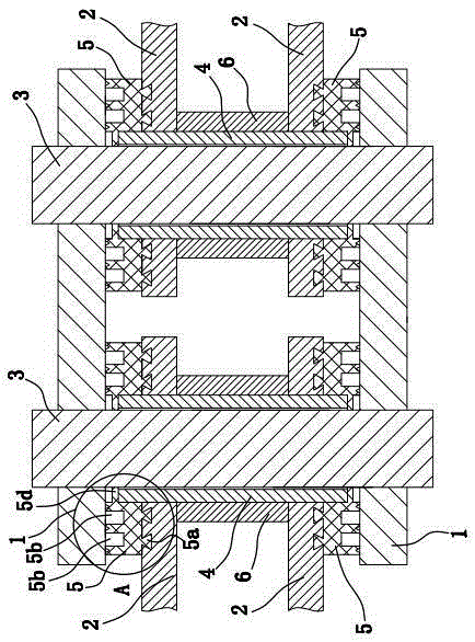
[0027] as shown in the picture 1 As shown, the sealing ring chain is composed of several chain units sequentially. Among them, each chain unit is composed of an outer chain plate 1 , inner chain plate 2 , pin 3 , bushing 4 , sealing ring 5 ,Roller 6 composition.

[0028] Specifically, the inner chain 2 There are two pieces, and two inner chain plates 2 Right on set. Bushing 4 Vertically installed on the two inner chain plates 2 between, and the shaft sleeve 4 The two ends of the two inner chain plates are connected respectively 2 phase fixed. Two inner chain plates 2 Outer chain plates are provided on the outside 1 , and two outer chain plates 1 Right on set. pin 3 inserted in the bushing 4 inner pin 3 Both ends protrude from the bushing 4 , and the pin 3 The two ends of the two outer chain plates are connected respectively 1 phase fixed. Roller 6 Cylindrical and set on the shaft sleeve 4 superior. ...

Embodiment 2

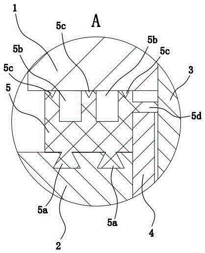
[0034] The structure and principle of the second embodiment are basically the same as that of the first embodiment, the difference is that the concave-convex connection structure includes 2 Connecting holes and sealing rings on the outer wall 5 Connecting posts matching the connecting holes on the top, the connecting holes have at least 2 indivual and along the sealing ring 5 Evenly distributed in the circumferential direction, the connecting hole is tapered and the diameter of the connecting hole gradually increases inwardly, the number of connecting posts is the same as that of the connecting holes and the positions correspond to each other, and the connecting posts are embedded in the connecting holes.


PUM


Abstract

The invention provides a sealing ring chain. By adoption of the sealing ring chain, the problem that existing sealing ring chains are short in service life is solved. The sealing ring chain is formed by sequentially combining a plurality of chain units. Each chain unit comprises two inner chain plates fixed through a shaft sleeve, wherein the outer sides of the two inner chain plates are each provided with an outer chain plate, and the two outer chain plates are fixed through a pin shaft which is sleeved with the shaft sleeve; and a sealing ring is arranged between each inner chain plate and the corresponding outer chain plate which are located on the same side and arranged on the shaft sleeve in a sleeving mode. The two end faces of the sealing rings are each a plane and are separately attached to the inner chain plates and the outer chain plates. The sealing rings are fixed to the inner chain plates through uneven connecting structures. At least two oil storage grooves and grooves which are each in an annular shape are formed in the end faces, making contact with the outer chain plates, of the sealing rings. All the oil storage grooves are concentrically distributed. Each groove is formed between every two corresponding adjacent oil storage grooves. The widths and the depths of the grooves are both larger than that of the oil storage grooves. The sealing ring chain has the advantage of long service life.

Description

technical field [0001] The invention belongs to a chain, in particular to a sealing ring chain. Background technique [0002] In the prior art, the sealing ring chain consists of an inner chain plate, an outer chain plate, a shaft sleeve, a pin shaft and O Type sealing ring and so on. in, O The type sealing ring is squeezed between the inner chain plate, the outer chain plate and the shaft sleeve, and these four form a closed space, so that the grease between the shaft sleeve and the pin shaft will not overflow during operation. [0003] In actual use, the elasticity, wear resistance and sealing performance of the sealing ring play an important role in the service life of the chain. and O There is a certain amount of deformation after being squeezed. Although its advantage is that the price is low, the wear resistance of this sealing ring is poor. After the grease evaporates, the chain will wear faster without lubrication, which cannot meet the market demand f...

Claims


Application Information

Patent Timeline
Patent Type & Authority Applications(China)
IPC IPC(8): F16G13/06F16G15/12
Inventor 梁海兵张艳凤
Owner TIANJIN QIANGLI CHAIN
Learn More