Hydrostatic driving movement gear shifting control method and system
A shift control, hydrostatic technology, applied in transmission control, components with teeth, belts/chains/gears, etc., can solve the problems of increasing total time, large engine load, overflow, etc., and achieve a simple and universal structure. , Reduce the shift time, the effect of smooth speed
Active Publication Date: 2017-05-31
WEICHAI POWER CO LTD
10 Cites 8 Cited by
AI-Extracted Technical Summary
Problems solved by technology
[0037] (1) First of all, in terms of system composition, this technology requires a gearbox with a synchronizer. Compared with a gearbox without a synchronizer, its disadvantages are high price and high failure rate
[0038] (2) During the shifting process, the control system needs to adjust the displacement of the motor to 0 first, and the displacement of the pump to 0 at the same time, otherwise the hydraulic oil output by the pump will quickly cause the overflow of the system, resulting in engine failure. heavy load
In this case, on the one hand, a certain overflow and energy loss will inevitably be caused during the shifting p...
Method used
In consideration of the variation of hydraulic pump and motor volumetric efficiency, the absolute value of the difference between nHM and nGearOut·new may be adjusted lower than the preset difference, and a closed-loop control pair can be added according to actual needs The actual motor speed is further fine-tuned, so as to achieve the purpose of fast synchronization. It is worth further explaining that the synchronous control needs to continue until step S305, so as to ensure that the speed synchronization is always maintained during the process of switching to the target gear.
[0151] Considering th...
Abstract
The invention discloses a hydrostatic driving movement gear shifting control method which comprises the steps of load reduction, neutral gear switching, synchronous control and target gear switching, wherein in the step of the load reduction, when gear shifting is required, differential pressure delta p between the high-pressure side and the low-pressure side of a motor is reduced; in the step of the neutral gear switching, a gear shifting actuator is switched to a neutral gear state when the delta p is reduced to preset differential pressure; in the step of the synchronous control, a rotating speed of the motor is controlled, and a rotating speed of an input shaft of a gearbox and a rotating speed of an output shaft of the gearbox are synchronized based on a target gear transmission ratio; and in the step of the target gear switching, the gear shifting actuator is switched to a target gear. The gearbox used in the hydrostatic driving movement gear shifting control method is not provided with a clutch or a synchronizer, is simple and universal in structure and low in cost, and has the comparative cost advantage in a hydrostatic driving solution, the whole gear shifting process can be realized completely automatically, the gear shifting time can be controlled within 500-800ms, and the gear shifting rapidity and the velocity smoothness in the gear shifting process are ensured. The invention further discloses a hydrostatic driving movement gear shifting control system.
Application Domain
Gearing control
Technology Topic
Gear transmissionShift time +8
Image
Examples
- Experimental program(1)
Example Embodiment
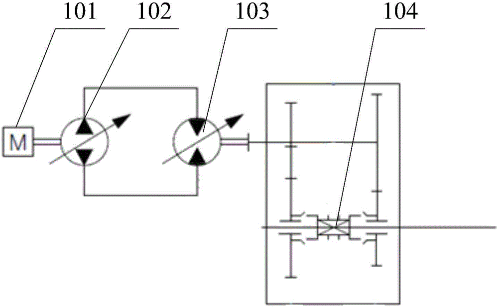
[0085] The core of the present invention is to provide a hydrostatic transmission moving shifting control method and system, so that a gearbox without a synchronizer can also realize shifting on the go, and at the same time, it is not necessary to adjust the displacement of the pump to 0, reducing the shifting speed. The total time required for the file.
[0086] Hereinafter, the embodiment will be described with reference to the drawings. In addition, the embodiments shown below do not have any limiting effect on the content of the invention described in the claims.
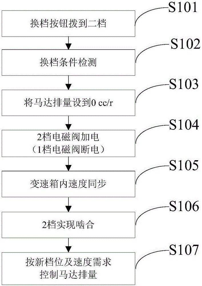
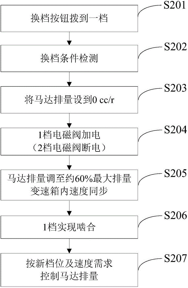
 In addition, the whole content of the structure shown in the following embodiment is not limited to what is necessary for the solution of the invention described in the claim.
[0087] see Figure 5 , Figure 5 This is a flow chart of the hydrostatic transmission shift control method provided by the embodiment of the present invention.
[0088] The embodiment of the present invention discloses a hydrostatic transmission mobile shifting control method, comprising the steps of:
[0089] S301: Shift switch request for shift switch;
[0090] Real-time detection of the driver's shift request, once the shift switch state changes (such as switching from 1st gear to 2nd gear, or from 2nd gear to 1st gear), or it detects that the gear switch state does not match the actual gear position, then The shifting process begins.
[0091] S302: Load reduction control of hydrostatic system;
[0092] Due to the rigid connection between the motor and the gearbox input shaft in the hydrostatic system, before shifting, the vehicle is in motion, and there is torque transmission between the motor and the gearbox input shaft, and the shift fork cannot be shifted from the old gear engagement. out, which is why the current solution requires the vehicle to stop and then shift gears. The hydrostatic load reduction is to reduce the torque between the motor and the gearbox input shaft to 0 (ideal state), usually it can be reduced to a preset value, which can be selected according to different vehicles, as long as it can be The shift fork can be pulled out of the old gear engagement. Since the output torque of the motor has a linear relationship with the displacement of the motor, reducing the torque output of the motor can reduce the pressure difference Δp between the high-pressure side and the low-pressure side of the motor when shifting is required. Decrease the pressure difference Δp.
[0093] Because in the hydrostatic drive solution, in a fixed gear, the vehicle speed is proportional to the displacement ratio of the hydraulic pump and the motor. The adjustment method of the hydraulic pump and the motor is to set the motor displacement to the maximum when starting. , the displacement of the hydraulic pump gradually increases from 0, and the speed of the vehicle gradually increases; when the displacement of the hydraulic pump reaches the maximum, the displacement of the motor begins to gradually decrease, and the speed of the vehicle continues to gradually increase. When the displacement of the motor reaches the minimum set value, the vehicle speed reaches maximum. During the whole process, the displacement ratio of hydraulic pump to motor is gradually increasing. Once the travel speed requirement is determined, the respective displacements of the hydraulic pump and motor can also be determined. The above travel speed requirement is the displacement ratio of the hydraulic pump to the motor. The conversion relationship between travel speed demand and hydraulic pump/motor displacement ratio can be calculated using the following formula:
[0094]
[0095] where r is the travel speed demand, q Pump_max is the maximum displacement of the pump, q Motor_min is the minimum set displacement of the motor, q Pump_max /q Motor_min It is the maximum adjustment ability of the hydraulic system to ensure that the vehicle reaches the maximum speed.
[0096]At the moment of entering the step of the load reduction control of the hydrostatic system, the driving speed demand is frozen, that is, the system no longer responds to the driver's driving demand. The hydrostatic system load reduction control performs closed-loop control of Δp on the basis of the frozen travel speed demand. When Δp>0, it will continue to reduce the travel speed demand; when Δp<0, it will continue to increase the travel speed demand. It is worth further explaining that the load reduction control of the hydrostatic system needs to continue until the switch to neutral is completed, so as to avoid that Δp exceeds the corresponding range during the process of switching to neutral.
[0097] S303: switch to neutral;
[0098] When the Δp is as low as the preset pressure difference, switch to the neutral state. The preset pressure difference needs to be set differently according to different vehicles, as long as it is ensured that the shift fork can be shifted from the meshing of the old gear. out. The range of the preset differential pressure can be -30bar~+30bar, that is, when Δp falls between -30bar~+30bar, it can switch to neutral state, or when the absolute value of Δp is lower than 30bar, switch to neutral state. It should be noted that the preset differential pressure is not limited to the range of -30bar to +30bar, and needs to be adjusted according to different vehicles, as long as the shift fork is disengaged and engaged.
[0099] S304: synchronous control;
[0100] After the control of S303, the motor has been disengaged from the output shaft of the gearbox, and the vehicle drives the output shaft of the gearbox to rotate under the action of inertia. To achieve the engagement of the new gear, it is necessary to control the motor speed to make it based on the gear ratio of the target gear and the gearbox. The output shaft is kept in sync. The control of the motor speed is achieved by adjusting the travel speed demand (ie the displacement ratio of the pump to the motor), because in the hydrostatic drive, the relationship between the speed of the motor and the displacement ratio of the hydraulic pump to the motor is as follows:
[0101]
[0102] In the formula, n Motor is the motor speed, n Diesel is the engine speed, q Pump is the set displacement of the pump, q Motor Set displacement for the motor.
[0103] S305: switch to the target gear;
[0104] The power-on state of the shift solenoid valve can be controlled, and the shift actuator drives the shift fork to switch to the target gear position.
[0105] S306: Control the hydraulic system according to the new gear and speed requirements;
[0106] The hydraulic system is controlled according to the new gear state and speed demand, and the displacement of the hydraulic pump and motor is adjusted according to the transmission ratio of the new gear to realize the speed control of the vehicle. In order to ensure the continuity of the vehicle speed at the moment of entering the new gear, it is necessary to adjust the displacement of the hydraulic pump and motor according to a certain slope, and gradually transition to the target hydraulic system adjustment amount.
[0107] The hydrostatic transmission shift control method provided by the present invention, when shifting is required, firstly performs a load reduction process, that is, reduces the pressure difference Δp between the high pressure side and the low pressure side of the motor, so that Δp is as low as the preset pressure difference, This reduces the torque applied by the motor to the gearbox or the torque applied by the gearbox to the motor so that the shift fork can be pulled out of the old gear engagement and then switched to neutral to cut off the transmission. Power transmission between input shaft and output shaft. Then control the speed of the motor, and make the speed of the input shaft of the gearbox synchronize with the speed of the output shaft of the gearbox under the premise of the gear ratio of the target gear, so that the shift fork can be toggled to mesh with the gear of the target gear, Avoid situations where you can't mesh or punch your teeth. In the present invention, the hydrostatic load reduction step realizes the function of the clutch, and the synchronization control step realizes the function of the synchronizer. It is only necessary to reduce the pressure difference between the high and low pressure sides of the motor, which reduces the shift time. The gearbox used in the invention does not have a clutch and a synchronizer, has a simple and common structure, and has a low cost. It has a considerable cost advantage in the hydrostatic drive solution, and the entire shifting process can be realized completely automatically, and the shifting time can be Between 500ms and 800ms, it can ensure the rapidity of shifting and the smoothness of the speed during shifting.
[0108] In a specific embodiment of the present invention, step S302 is specifically:
[0109] If the vehicle is accelerating or driving at a constant speed before shifting, it means that the motor drives the gearbox to rotate. At this time, Δp>0, the driving speed of the vehicle is reduced; if the vehicle is decelerating or braking before shifting, it means that the motor is being driven by the gearbox. , at this time Δp<0, then increase the speed of the vehicle.
[0110] In a specific embodiment of the present invention, closed-loop control is adopted for the adjustment of Δp, the input is Δp, and the output is the adjustment amount of the traveling speed demand, which is superimposed with the traveling speed before load reduction to obtain the control of the hydraulic pump or motor. displacement. Once the absolute value of Δp is detected to be lower than the preset differential pressure, it indicates that the mutual torque between the motor and the gearbox is small enough to allow the shift fork to easily disengage and return to the neutral position.
[0111] Preferably, the speed of the input shaft of the gearbox is synchronized with the speed of the output shaft of the gearbox as: n HM with n GearOut ·i new The absolute value of the difference is lower than the preset difference, you can turn the shift fork to engage with the gear of the target gear, n HM is the motor speed, n GearOut ·i new It is the product of the transmission output shaft speed and the new gear ratio. The preset difference value can be set according to different vehicles, as long as it can ensure that the shift fork can be easily disengaged and engaged.
[0112] Taking into account the changes in the volumetric efficiency of the hydraulic pump and motor, the single pass lets n HM with n GearOut ·i new If the absolute value of the difference is lower than the preset difference, there may be deviations. According to actual needs, a closed-loop control can be added to further fine-tune the actual motor speed, so as to achieve the purpose of quickly achieving synchronization. It is worth further explaining that the synchronization control needs to continue until step S305, so as to ensure that the speed synchronization is always maintained during the process of switching to the target gear.
[0113] Another embodiment of the present invention discloses a hydrostatic transmission shifting control method, comprising the steps of:
[0114] S401: Shift switch request for shift switch;
[0115] Real-time detection of the driver's shift request, once the shift switch state changes (such as switching from 1st gear to 2nd gear, or from 2nd gear to 1st gear), or it detects that the gear switch state does not match the actual gear position, then The shifting process begins.
[0116] S402: Shift condition detection;
[0117] When the shifting conditions are satisfied, step S403 is performed, and the shifting conditions include:
[0118] 1) Due to the change of the transmission ratio of the gearbox before and after shifting, on the premise of maintaining the current vehicle speed, the required adjustment amount of the hydrostatic system can be within its adjustment range;
[0119] 2) Due to the change of transmission ratio before and after shifting, the pressure of the hydrostatic system will not exceed the maximum limit pressure of the system under the premise of maintaining the current load.
[0120] S403: load reduction control of hydrostatic system;
[0121] Due to the rigid connection between the motor and the gearbox input shaft in the hydrostatic system, before shifting, the vehicle is in motion, and there is torque transmission between the motor and the gearbox input shaft, and the shift fork cannot be shifted from the old gear engagement. out, which is why the current solution requires the vehicle to stop and then shift gears. The hydrostatic load reduction is to reduce the torque between the motor and the gearbox input shaft to 0 (ideal state), usually it can be reduced to a preset value, which can be selected according to different vehicles, as long as it can be The shift fork can be pulled out of the old gear engagement. Since the output torque of the motor has a linear relationship with the displacement of the motor, reducing the torque output of the motor when shifting is required can reduce the pressure difference Δp between the high-pressure side and the low-pressure side of the motor. Decrease the pressure difference Δp.
[0122] S404: switch to neutral;
[0123] When the Δp is as low as the preset pressure difference, switch to the neutral state. The preset pressure difference needs to be set differently according to different vehicles, as long as it is ensured that the shift fork can be shifted from the meshing of the old gear. out. The range of the preset differential pressure can be -30bar~+30bar, that is, when Δp falls between -30bar~+30bar, it can switch to neutral state, or when the absolute value of Δp is lower than 30bar, switch to neutral state. It should be noted that the preset differential pressure is not limited to the range of -30bar to +30bar, and needs to be adjusted according to different vehicles, as long as the shift fork is disengaged and engaged.
[0124] S405: synchronous control;
[0125] After the control of S404, the motor has been disengaged from the output shaft of the gearbox, and the vehicle drives the output shaft of the gearbox to rotate under the action of inertia. To realize the engagement of the new gear, it is necessary to control the speed of the motor to make it based on the gear ratio of the target gear and the gearbox. The output shaft is kept in sync. The control of the motor speed is achieved by adjusting the travel speed demand (ie the displacement ratio of the pump to the motor), because in the hydrostatic drive, the relationship between the speed of the motor and the displacement ratio of the hydraulic pump to the motor is as follows:
[0126]
[0127] In the formula, n Motor is the motor speed, n Diesel is the engine speed, q Pump is the set displacement of the pump, q Motor Set displacement for the motor.
[0128] S406: switch to the target gear;
[0129] The power-on state of the shift solenoid valve can be controlled, and the shift actuator drives the shift fork to switch to the target gear position.
[0130] S407: Control the hydraulic system according to the new gear and speed requirements;
[0131] The hydraulic system is controlled according to the new gear state and speed demand, and the displacement of the hydraulic pump and motor is adjusted according to the transmission ratio of the new gear to realize the speed control of the vehicle. In order to ensure the continuity of the vehicle speed at the moment of entering the new gear, it is necessary to adjust the displacement of the hydraulic pump and motor according to a certain slope, and gradually transition to the target hydraulic system adjustment amount.
[0132] In order to avoid the situation that a certain step cannot be completed all the time due to abnormal conditions such as failure of some components, resulting in a deadlock in the control process, in a specific embodiment of the present invention, a timing step is further included, and the timing step is used for dividing the timing. The other steps other than the step are timed. If the step is not completed within the preset time, a timeout fault of the step will be reported to remind the driver to restart or troubleshoot maintenance.
[0133] When the vehicle is stationary, it is detected that the gear position is in the neutral state (for example, the last gear shift process just switched to neutral but was interrupted abnormally), special handling is required for this situation. At this time, if there is a shift request, the switch to neutral and the previous steps are equivalent to have been automatically completed. At this time, the synchronous control step is entered. Since the vehicle is stationary, if the speed synchronous control will keep the motor stationary and enter the switch to the target gear. However, if the key teeth of the shift fork are not aligned with the key groove of the target gear at this time, the action of controlling the shift actuator to switch the gear to the target gear will definitely not be realized, and will eventually lead to the gear shifting process. report an error.
[0134]Therefore, in this case, the speed synchronization method is not to keep the motor stationary, but to let the hydraulic pump have a small displacement (that is, to control the hydraulic pump to work at a preset displacement), let the motor rotate at a small speed, and change the displacement at the same time. The shift actuator pushes the shift fork, and once the key teeth and keyways are aligned, the shift to the target gear can be accomplished without a hitch. The preset displacement does not need to be too large, as long as the motor rotates a small angle, the key teeth and key grooves can be aligned, so that the shift actuator can push the shift fork to shift.
[0135] see Figure 4 , Figure 4 This is a schematic structural diagram of a hydrostatic transmission system provided by an embodiment of the present invention.
[0136] The hydrostatic transmission shift control system disclosed in the embodiment of the present invention includes a pressure sensor 211 , an input rotational speed sensor 212 , an output rotational speed sensor 208 and a controller 203 .
[0137] The pressure sensors 211 are two for detecting the pressure of the high pressure side and the low pressure side of the motor, respectively. The input rotational speed sensor 212 is used to detect the rotational speed of the motor 202 or the input shaft of the gearbox, and the rotational speed detected by the input rotational speed sensor 212 is the first rotational speed; the output rotational speed sensor 208 is used to detect the rotational speed of the output shaft of the gearbox, and the output rotational speed sensor 208 detects The obtained speed value is the second speed.
[0138] When the state of the shift switch 204 of the vehicle changes, the controller 203 is used to adjust the running speed of the vehicle to reduce the pressure difference Δp between the high pressure side and the low pressure side of the motor 202, and when Δp is lower than the preset pressure difference, control the The shift actuator 207 of the gearbox switches to the neutral state (the shift actuator 207 controls the action through the shift solenoid valve 206), and then controls the rotational speed of the motor 202 to make the first rotational speed based on the target gear ratio. Synchronized with the second rotational speed, the shift actuator 207 is then controlled to switch to the target gear.
[0139] Since the motor 202 in the hydrostatic system is rigidly connected to the input shaft of the transmission, before shifting, the vehicle is in motion, and there is torque transmission between the motor 202 and the input shaft of the transmission, and the shift fork 209 cannot be shifted from the old gear. Dial out in engagement, which is why current solutions require the vehicle to come to a standstill before shifting. The hydrostatic load reduction is to reduce the torque between the motor 202 and the transmission input shaft to 0 (ideal state), usually it can be reduced to a preset value, which can be selected according to different vehicles, as long as it can be guaranteed Just pull the shift fork 209 out of the old range gear engagement. Since the output torque of the motor 202 has a linear relationship with the displacement of the motor 202, when gear shifting is required, reducing the torque output of the motor 202 can reduce the pressure difference Δp between the high pressure side and the low pressure side of the motor 202. Specifically, it can be adjusted by adjusting The vehicle travel speed mode reduces the pressure difference Δp.
[0140] When the Δp is lower than the preset pressure difference, switch to the neutral state. The preset pressure difference needs to be set differently according to different vehicles, as long as it is ensured that the shift fork 209 can be meshed from the old gear gear. Just dial out. The range of the preset differential pressure can be -30bar~+30bar, that is, when Δp falls between -30bar~+30bar, it can switch to neutral state, or when the absolute value of Δp is lower than 30bar, switch to neutral state. It should be noted that the preset differential pressure is not limited to the range of -30bar to +30bar, and needs to be adjusted according to different vehicles, as long as the shift fork 209 is disengaged and engaged.
[0141] After the controller 203 controls the shift actuator 207 of the gearbox to switch to the neutral state, the motor 202 has been disengaged from the gearbox output shaft 210, and the vehicle drives the gearbox output shaft 210 to rotate under the action of inertia. To engage, it is necessary to control the motor speed to synchronize the gear ratio based on the target gear with the output shaft of the gearbox. The control of the motor speed is achieved by adjusting the travel speed requirement (ie the displacement ratio of the hydraulic pump 201 to the motor 202), because in the hydrostatic drive, the relationship between the speed of the motor 202 and the displacement ratio of the hydraulic pump 201 to the motor is as follows:
[0142]
[0143] In the formula, n Motor is the motor speed, n Diesel is the engine speed, q Pump is the set displacement of the pump, q Motor Set displacement for the motor.
[0144] After the controller 203 controls the shift actuator 207 to switch to the target gear, the displacement of the hydraulic pump 201 and the motor 202 is adjusted according to the transmission ratio of the new gear to control the speed of the vehicle. In order to ensure the vehicle speed continuity at the moment of entering the new gear, it is necessary to adjust the displacement of the hydraulic pump 201 and the motor 202 according to a certain slope, and gradually transition to the target hydraulic system adjustment amount.
[0145] Since in the hydrostatic drive solution, in a fixed gear, the vehicle speed is proportional to the displacement ratio of the hydraulic pump 201 and the motor 202, the adjustment method of the hydraulic pump 201 and the motor 202 is: when starting, the motor is discharged first. The displacement is set to the maximum, the displacement of the hydraulic pump 201 gradually increases from 0, and the vehicle speed gradually increases; when the displacement of the hydraulic pump 201 reaches the maximum, the displacement of the motor 202 begins to gradually decrease, and the vehicle speed continues to gradually increase. When the displacement reaches the minimum set value, the vehicle speed reaches the maximum. Throughout the process, the displacement ratio of the hydraulic pump 201 to the motor 202 is gradually increasing. Once the travel speed requirement is determined, the respective displacements of the hydraulic pump 201 and the motor 202 can also be determined. The above travel speed requirement is the displacement ratio of the hydraulic pump 201 and the motor 202 . The conversion relationship between travel speed demand and hydraulic pump/motor displacement ratio can be calculated using the following formula:
[0146]
[0147] where r is the travel speed demand, q Pump_max is the maximum displacement of the pump, q Motor_min is the minimum set displacement of the motor, q Pump_max /q Motor_min It is the maximum adjustment ability of the hydraulic system to ensure that the vehicle reaches the maximum speed.
[0148] At the moment of entering the command of the load reduction control of the hydrostatic system, the driving speed demand is frozen, that is, the system no longer responds to the driver's driving demand. The hydrostatic system load reduction control performs closed-loop control of Δp on the basis of the frozen travel speed demand. When Δp>0, it will continue to reduce the travel speed demand; when Δp<0, it will continue to increase the travel speed demand. It is worth further explaining that the load reduction control of the hydrostatic system needs to continue until the switch to neutral is completed, so as to avoid that Δp exceeds the corresponding range during the process of switching to neutral.
[0149] In a specific embodiment of the present invention, when the state of the shift switch 204 of the vehicle changes, the controller 203 is configured to reduce the output displacement of the hydraulic pump 201 when Δp>0; and increase the hydraulic pump when Δp<0 201's output displacement. If the vehicle is accelerating or driving at a constant speed before shifting, it means that the motor 202 drives the gearbox to rotate, and at this time Δp>0, the speed of the vehicle is reduced; if the vehicle is decelerating or braking before shifting, it means that the motor 202 is shifting If the box is pushed, at this time Δp<0, the speed of the vehicle is increased.
[0150] In a specific embodiment of the present invention, the synchronization between the first rotational speed and the second rotational speed is based on the target gear transmission ratio as follows: n HM with n GearOut ·i new The absolute value of the difference is lower than the preset difference; where, n HM is the motor speed, n GearOut ·i new It is the product of the transmission output shaft speed and the new gear ratio. The preset difference value can be set according to different vehicles, as long as it can ensure that the shift fork can be easily disengaged and engaged.
[0151] Considering the change of the volumetric efficiency of the hydraulic pump 201 and the motor 202, the single pass lets n HM with n GearOut ·i new If the absolute value of the difference is lower than the preset difference, there may be deviations. According to actual needs, a closed-loop control can be added to further fine-tune the actual motor speed, so as to achieve the purpose of quickly achieving synchronization. It is worth further explaining that the synchronization control needs to continue until step S305, so as to ensure that the speed synchronization is always maintained during the process of switching to the target gear.
[0152] In a specific embodiment of the present invention, the controller 203 is also used for judging the shifting conditions, and the shifting control is performed only when the shifting conditions are satisfied. The shifting conditions include:
[0153] 1) Due to the change of the transmission ratio of the gearbox before and after shifting, on the premise of maintaining the current vehicle speed, the required adjustment amount of the hydrostatic system can be within its adjustment range;
[0154] 2) Due to the change of transmission ratio before and after shifting, the pressure of the hydrostatic system will not exceed the maximum limit pressure of the system under the premise of maintaining the current load.
[0155] In a specific embodiment of the present invention, the present invention further includes a gear position sensor 205 for detecting the gear position of the gearbox, and the controller 203 is used for when the state of the shift switch 204 changes or does not match the actual gear position , then the shift condition judgment is performed. The detection amount of the gear position sensor 205 can also be used as a basis for the controller 203 to execute the next command. For example, the controller 203 controls the gear shift actuator 207 of the gearbox to switch to the neutral state, and when the gear position sensor 205 detects that the gearbox is in the neutral state, it controls the speed of the motor 202, based on the premise of the target gear ratio , so that the first rotational speed is synchronized with the second rotational speed, and then the shift actuator 207 is controlled to switch to the target gear. When the gear position sensor 205 detects that the gearbox is in the target gear, the displacement of the hydraulic pump 201 and the motor 202 is adjusted according to the transmission ratio of the new gear to control the speed of the vehicle.
[0156] It should be noted that the gear position sensor 205 can detect the state of the first gear, the second gear or the neutral gear of the gearbox. Since the four-speed gearbox requires two shift forks, the fourth-speed gearbox requires two gears. position sensor.
[0157] In a specific embodiment of the present invention, when the vehicle is stationary, if a gear shift is required and the vehicle is in a neutral state, the controller 203 controls the hydraulic pump to work at a preset displacement, and then controls the shift actuator 207 to switch to the target gear position . When the vehicle is stationary, it is detected that the gear is in the neutral state (for example, the shift to neutral is abnormally interrupted during the last shift process), special handling is required for this situation. If there is a shift request at this time, the controller executes the synchronous control command at this time, and since the vehicle is stationary, if the speed synchronous control keeps the motor 202 stationary and enters the shift to the target gear. However, if the key teeth of the shift fork 209 are not aligned with the key grooves of the target gear at this time, the action of controlling the shift actuator 207 to switch the gear to the target gear will definitely not be realized, and will eventually lead to shifting. process error.
[0158] Therefore, in this case, the speed synchronization method is not to keep the motor stationary, but to allow the hydraulic pump 201 to have a small displacement (that is, to control the hydraulic pump 201 to work at a preset displacement), and to make the motor 202 rotate at a small speed. , while the shift actuator 207 pushes the shift fork 209, once the key teeth and the key groove are aligned, the shift to the target gear can be successfully completed. The preset displacement does not need to be too large, as long as the motor 202 rotates by a small angle, the key teeth and the key grooves can be aligned, so that the shift actuator 207 can push the shift fork 209 to shift gears.
[0159] In order to avoid the situation that a certain step cannot be completed all the time due to abnormal conditions such as failure of some components, resulting in a deadlock in the control process, in a specific embodiment of the present invention, a timer is also included, and the timer is used for the controller 203 The execution time of each instruction is timed. If the instruction is not completed within the preset time, the instruction timeout fault will be reported to remind the driver to restart or troubleshoot maintenance.
[0160]The controller 203 of the present invention controls the displacement of the hydraulic pump and the motor through the corresponding solenoid valves of the hydraulic pump and the motor.
[0161] The control of the shift actuator 207 is further explained, because the mobile shift technology can support two-speed or four-speed gearbox, and each shift actuator 207 can support the left and right movement of one hydraulic valve, that is, one shift The shift fork 209 moves between the two gears and neutral, so if the two-speed gearbox scheme is selected, the system needs a shift actuator 207; if the four-speed gearbox scheme is selected, the system needs two gearshifts Actuator 207. For a certain shift actuator 207, if the control current of the neutral position is N, the control current of the low position is L, and the control current of the high position is H, then for a four-speed gearbox, the control combination of the shift actuator is different from that of the gears. The corresponding relationship of the bits can be shown by the following table:
[0162]
[0163] The above description of the disclosed embodiments enables any person skilled in the art to make or use the present invention. Various modifications to these embodiments will be readily apparent to those skilled in the art, and the generic principles defined herein may be implemented in other embodiments without departing from the spirit or scope of the invention. Thus, the present invention is not intended to be limited to the embodiments shown herein, but is to be accorded the widest scope consistent with the principles and novel features disclosed herein.
PUM


Description & Claims & Application Information
We can also present the details of the Description, Claims and Application information to help users get a comprehensive understanding of the technical details of the patent, such as background art, summary of invention, brief description of drawings, description of embodiments, and other original content. On the other hand, users can also determine the specific scope of protection of the technology through the list of claims; as well as understand the changes in the life cycle of the technology with the presentation of the patent timeline. Login to view more.
Similar technology patents
Vehicle gear shifting method and device
ActiveCN112046485Ashorten shift timeImprove driving satisfaction
Owner:NANJING UNIV OF AERONAUTICS & ASTRONAUTICS
Novel hydraulic gear-shifting pressure regulating valve
InactiveCN102788150Ashorten shift time
Owner:SICHUAN UNIV
Control method for non-simple gear shifting of automatic speed changer
ActiveCN108006218Ashorten shift timeImprove power performance
Owner:SHENGRUI TRANSMISSION
Hybrid vehicle, and shifting control method and system thereof
ActiveCN109572699Ashorten shift timeImprove driving experience
Owner:BYD CO LTD
Method for operating a drive train
Owner:ZF FRIEDRICHSHAFEN AG
Classification and recommendation of technical efficacy words
- shorten shift time
Shifting method for AMT (Automated Mechanical Transmission) automatic gearbox
ActiveCN103697154ASmall shift shockshorten shift time
Owner:ZHEJIANG GEELY HLDG GRP CO LTD +1
Method for operating a drive train
Owner:ZF FRIEDRICHSHAFEN AG
Hybrid vehicle, and shifting control method and system thereof
ActiveCN109572699Ashorten shift timeImprove driving experience
Owner:BYD CO LTD
Novel hydraulic gear-shifting pressure regulating valve
InactiveCN102788150Ashorten shift time
Owner:SICHUAN UNIV
Control method for non-simple gear shifting of automatic speed changer
ActiveCN108006218Ashorten shift timeImprove power performance
Owner:SHENGRUI TRANSMISSION