
Direction-adjustable and highly-protective solar LED street lamp

An LED street light, protective technology, applied in the direction of climate sustainability, energy-saving lighting, sustainable buildings, etc., can solve the problems of economic loss, easy damage, complex structure, etc., to reduce economic loss, high service life, production low cost effect

Active Publication Date: 2017-05-31
HAOERSAI LIGHTING TECH GRP
View PDF5 Cites 4 Cited by
  • Summary
  • Abstract
  • Description
  • Claims
  • Application Information

AI Technical Summary

Problems solved by technology

[0002] Solar street lights must use solar cell components to provide electrical energy. For different regions and seasons, the installation inclination and azimuth of solar cell components are different. Traditional solar LED street lights have a single fixing method and complex structures. The adjustment angle is limited, so Can not get sufficient lighting effect, so can not fully perform photoelectric conversion, resulting in low conversion utilization rate of solar energy, and, due to the large area of ​​the solar panel, and the complex structure, it is easy to be affected by climatic factors such as wind and sand and dust. impact, under some extreme conditions, it is highly prone to damage
This caused economic loss and affected the normal traffic of the road

Method used


Image

  • Direction-adjustable and highly-protective solar LED street lamp
  • Direction-adjustable and highly-protective solar LED street lamp
  • Direction-adjustable and highly-protective solar LED street lamp

Examples


Embodiment Construction

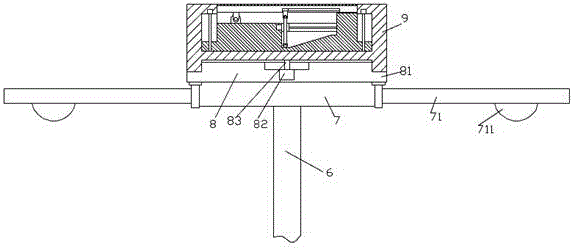
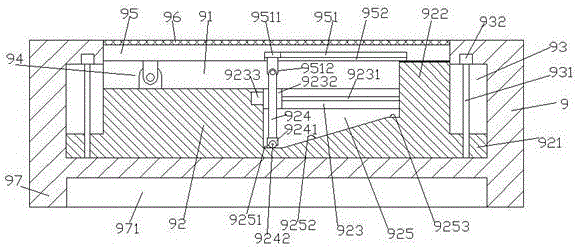
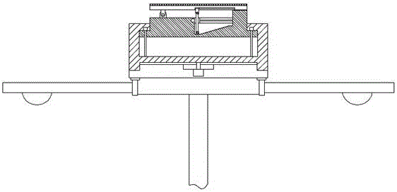
[0022] like Figure 1-Figure 5 As shown, an azimuth-adjustable and highly protective solar LED street lamp of the present invention includes a lamp post 6, a base 7 fixed on the top of the lamp post 6, and a driving base 8 fixed on the top of the base 7, The outer circumference of the driving base 8 is fixed with a guide ring 81 , and the middle position inside the driving base 8 is provided with a third motor 82 , and the top of the third motor 82 is rotatably connected with a rotating shaft extending upward. 83. An installation box 9 is provided above the drive bottom bracket 8, the top of the rotating shaft 83 is fixedly connected to the middle position of the bottom of the installation box 9, and the bottom edge of the installation box 9 is fixed with a convex ring sliding Block 97, the ring-shaped slider 97 is provided with an annular groove 971, the top of the drive base 8 extends into the ring-shaped groove 971 and is connected in a rotational fit, the bottom end surfac...


PUM


Abstract

The invention discloses a direction-adjustable and highly-protective solar LED street lamp. The solar LED street lamp comprises a lamp post, a base fixed to the top of the lamp post and a driving bottom support fixed to the top of the base, wherein a guiding and sliding convex ring is fixedly arranged in the circumferential direction of the outer side of the driving bottom support; a third motor is arranged in the middle position of the interior of the driving bottom support; a rotating shaft extending upwardly is connected to the top of the third motor in a rotating manner; a mounting box body is arranged above the driving bottom support; the top end of the rotating shaft is fixedly connected with the middle position of the bottom of the mounting box body; a convex ring sliding block is fixedly arranged at the edge of the bottom of the mounting box body; a circular groove is formed in the convex ring sliding block; the top of the driving bottom support extends into the circular groove and is connected with the circular groove in a rotating and matching manner; the bottom end surface of the convex ring sliding block is butted against the top end surface of the guiding and sliding convex ring, and is connected with the top end surface of the guiding and sliding convex ring in a rotating and matching manner; a mounting groove is formed in the top of the interior of the mounting box body; and a lifting base is arranged in the mounting groove. The solar LED street lamp disclosed by the invention is simple in structure, convenient to operate, low in making cost, and long in service life, and economic loss is reduced.

Description

technical field [0001] The invention relates to the technical field of LED street lamps, in particular to a solar LED street lamp with adjustable orientation and high protection. Background technique [0002] Solar street lights must use solar cell components to provide electrical energy. For different regions and seasons, the installation inclination and azimuth of solar cell components are different. Traditional solar LED street lights have a single fixing method and complex structures. The adjustment angle is limited, so Can not get sufficient lighting effect, so can not fully perform photoelectric conversion, resulting in low conversion utilization rate of solar energy, and, due to the large area of ​​the solar panel, and the complex structure, it is easy to be affected by climatic factors such as wind and sand and dust. In some extreme conditions, it is easy to be damaged. This caused economic loss and affected the normal traffic of the road. Contents of the inventio...

Claims


Application Information

Patent Timeline
Patent Type & Authority Applications(China)
IPC IPC(8): F21S8/08F21S9/03H02S20/30F21Y115/10F21W131/103
CPCF21S8/086F21S9/035F21W2131/103H02S20/30Y02B20/72Y02E10/50
Inventor 俞陈
Owner HAOERSAI LIGHTING TECH GRP
Learn More