
Magnetization cracking device with stirring mechanism

A cracking device and stirring mechanism technology, applied in the direction of incinerators, combustion methods, lighting and heating equipment, etc., can solve the problem of comprehensive utilization of heat recovery, tail gas treatment methods, and undisclosed magnetization cracking. Uniform and effective technical solutions and other problems to achieve the effect of avoiding secondary pollution and fully effective magnetization cracking

Pending Publication Date: 2017-05-31
鑫源昊(浙江)环保能源科技有限公司
View PDF13 Cites 7 Cited by
  • Summary
  • Abstract
  • Description
  • Claims
  • Application Information

AI Technical Summary

Problems solved by technology

And the tail gas shown in the accompanying drawings needs to be purified, but the specific tail gas treatment method is not disclosed in its disclosed technical solution
[0007] Invention patent CN201510587612.X and utility model patent CN201520715048.0 disclose a magnetization cracking device, which contains tail gas treatment, but does not recover heat for comprehensive utilization, and does not disclose a technical solution to make magnetization cracking more uniform and effective

Method used


Image

  • Magnetization cracking device with stirring mechanism
  • Magnetization cracking device with stirring mechanism

Examples


Embodiment Construction

[0040]A tail gas treatment device and tail gas treatment method suitable for magnetization cracking of the present application will be described in more detail below in conjunction with the accompanying drawings.

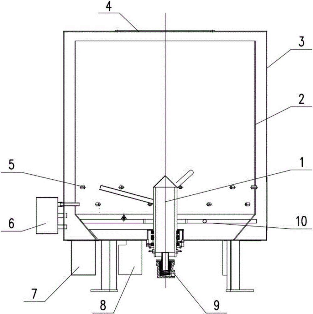
[0041] figure 1 It is a structural schematic diagram of a magnetic cracking device with a stirring mechanism in the present invention.

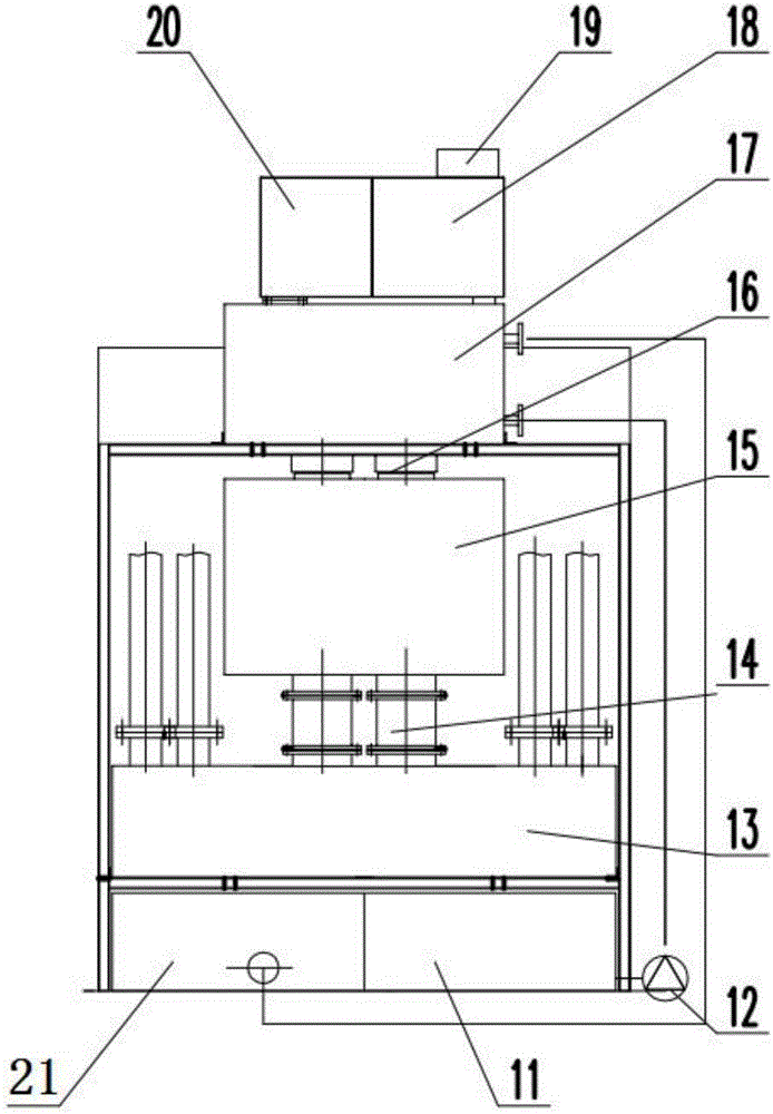
[0042] figure 2 It is a structural schematic diagram of a tail gas treatment device of a magnetic cracking device with a stirring mechanism in the present invention.

[0043] Such as figure 1 and figure 2 As shown, the present invention relates to a magnetization cracking device with a stirring mechanism, comprising a stirring shaft 1, an inner tank 2, an outer tank 3, a feeding port 4, an air inlet 5, a magnetization tank 6, a water tank 7, an ash tank 8, The rotary joint 9 and the furnace grate 10 can supply magnetized air to the cracking chamber in a balanced manner, and are equipped with a stirring device, which makes the...


PUM


Abstract

The invention discloses a magnetization cracking device with a stirring mechanism. Discharged tail gas meets the national standard requirement, harmful gas does not need to be separated from primary air, the harmful gas is directly converted into harmless matter, secondary pollution is avoided, and heat can also be recycled to be comprehensively utilized. The lower end of an inner container is connected to the bottom of an outer container in a sealed manner, and multiple air inlets are formed in the lower end of the inner container. The upper end of the outer container is movably connected with a feeding port, and multiple magnetization boxes are fixedly connected to the outer side of the outer container. The magnetization boxes are connected with the air inlets through pipelines. A stirring shaft is movably connected to the middle position of the bottom of the inner container and the middle position of the bottom of the outer container. A through ventilation hole is formed in the stirring shaft, and the inlet end of the ventilation hole is connected with a rotating connector. The stirring shaft is fixedly connected with multiple tentacle branches and a scraper plate. A grate is arranged at the lower end of the inner container, and the grate is arranged at the position, between the tentacle branches and the scraper plate, on the stirring shaft in a sleeving manner. The bottom of the outer container is provided with an ash outlet and a water outlet. An ash box and a water box are connected to the position under the ash outlet and the position under the water outlet of the bottom of the outer container correspondingly.

Description

technical field [0001] The invention relates to a magnetization cracking device, in particular to a magnetization cracking device with a stirring mechanism. Background technique [0002] The traditional methods of waste disposal include landfill and incineration. The two treatment methods for medical waste, waste tires and other plastic products, rubber products and other organic matters will cause certain secondary pollution, especially in the process of incineration of organic matters such as HCI, SO x , NO x Such acid gases, highly toxic chlorine-containing polymer compounds are collectively referred to as dioxins, and dust, etc., causing serious air pollution. In order to overcome the shortcomings of waste incineration technology, waste magnetization cracking technology has been developed. [0003] Inject a certain amount of strong magnetized air into the airtight device body to form an ionized space, and then inject a small amount of oxygen to make the oxygen molecule...

Claims


Application Information

Patent Timeline
Patent Type & Authority Applications(China)
IPC IPC(8): F23G5/027F23G5/18F23G5/44F23G5/46F23J15/04
CPCF23G5/027F23G5/18F23G5/44F23G5/46F23J15/04F23G2201/303F23G2201/302F23J2217/50
Inventor 王金民
Owner 鑫源昊(浙江)环保能源科技有限公司
Learn More