
Method of automatically blind pixel detecting and compensating in infrared focal plane array

A technology of infrared focal plane and compensation method, which is applied in the field of automatic blind element detection and compensation of infrared focal plane array, can solve the problems of poor detection effect of blind element blocks and single assumption, and achieves the effect of good detection effect and improved imaging quality.

Active Publication Date: 2017-05-31
ZHEJIANG ULIRVISION TECH
View PDF5 Cites 21 Cited by
  • Summary
  • Abstract
  • Description
  • Claims
  • Application Information

AI Technical Summary

Problems solved by technology

The assumption of the blind element detection method in the prior art is relatively simple, and the detection effect of the blind element block is poor

Method used


Image

  • Method of automatically blind pixel detecting and compensating in infrared focal plane array
  • Method of automatically blind pixel detecting and compensating in infrared focal plane array
  • Method of automatically blind pixel detecting and compensating in infrared focal plane array

Examples


Embodiment Construction

[0011] The present invention will be further described below in conjunction with accompanying drawing:

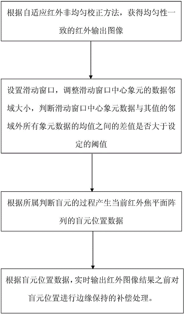
[0012] As shown in the figure, this infrared focal plane array automatic blind element detection and compensation method, the specific steps are as follows:

[0013] (1) Obtain an infrared output image with consistent uniformity according to the adaptive infrared non-uniformity correction method;

[0014] (2) Set the sliding window, adjust the size of the data neighborhood of the center pixel of the sliding window, and judge whether the difference between the mean value of all pixel data outside the neighborhood of the center pixel data of the sliding window and its value is greater than the set threshold, If the difference is greater than the set threshold, the center pixel of the current sliding window is a blind pixel;

[0015] (3) Generate the blind element position data of the current infrared focal plane array according to the process of judging the blind element;

...


PUM


Abstract

The invention relates to a method of automatically blind pixel detecting and compensating in infrared focal plane array. And the method comprises the following steps: (1) obtaining the infrared images with consistent homogeneity according to the adaptive infrared non-uniformity correction method, (2) installing the sliding window and resizing the data neighborhood of the center pixel of the sliding window and then judging whether the difference between the data of the center pixel of the sliding window and all mean values of the pixel data outside the neighborhood of the value is greater than the set threshold. If the difference is greater than the set threshold, the current center pixel in the sliding window is the blind pixel. The method of automatically blind pixel detecting and compensating in infrared focal plane array has the advantages that on the one hand the method is capable of providing an effective detection to the distribution of the blind pixel owned complicated conditions, and on the other hand edge preserving the blind pixel compensation, which owns better detection to the blind pixel block and develops the imaging quality of the thermal imager.

Description

technical field [0001] The invention relates to the technical field of blind element detection and compensation, in particular to an infrared focal plane array automatic blind element detection and compensation method. Background technique [0002] Blind elements refer to non-uniform or invalid pixel elements of the infrared focal plane array. Due to insurmountable defects in infrared detector manufacturing materials and processes, the larger the manufactured infrared detector array, the more failed pixels it contains. Therefore, for infrared detectors, the detection and compensation of blind elements has become one of the important measures to improve the imaging quality of thermal imagers. The blind element detection method in the prior art assumes a single assumption, and aims at the phenomenon that the detection effect of the blind element block is poor. Contents of the invention [0003] The present invention aims to solve the above-mentioned shortcomings of the pri...

Claims


Application Information

Patent Timeline
IPC IPC(8): G01J5/10
CPCG01J5/10G01J2005/0077G01J2005/106
Inventor 黄红友
Owner ZHEJIANG ULIRVISION TECH
Learn More