Flat UV light source

a light source and flat technology, applied in the field of flat uv light sources, can solve the problems of inability to generate radiation intensity that is necessary for industrial purposes, in particular for the drying of uv printing-inks, and is not suitable for use in optical radiation measurement, etc., and achieves the effect of simple led mounting, cooled very effectively and intensely

Inactive Publication Date: 2011-03-22
PLATSCH
View PDF14 Cites 16 Cited by
  • Summary
  • Abstract
  • Description
  • Claims
  • Application Information

AI Technical Summary

Benefits of technology

[0007]A further development of the invention includes a light-source wherein the light-emitting diodes are arranged in a densely packed manner, which is advantageous with regard to attaining a high radiation density and with regard to uniformity of the radiation field that is generated.
[0047]The further development of the invention includes a light-source characterised in that the power-supply contacts to be poled differently of adjacent light-emitting diodes are connected to one another via conductive tracks of a printed connecting pcb. This has the advantage that the failure of a single light-emitting diode results only in a slight change in the total quantity of light emitted in the light-source.

Problems solved by technology

For the purpose of operating mercury-vapour lamps of such a type, expensive and bulky mains power packs are necessary, which have to provide a high igniting voltage a maintaining voltage.
However, with such flat UV light sources the radiation intensity that are necessary for industrial purposes, in particular for the drying of UV printing-inks, cannot be generated.

Method used


Image

  • Flat UV light source
  • Flat UV light source
  • Flat UV light source

Examples


Embodiment Construction

[0072]While this invention is susceptible of embodiment in many different forms, there is shown in the drawings and will herein be described in detail one or more embodiments with the understanding that the present disclosure is to be considered as an exemplification of the principles of the invention and is not intended to limit the invention to the embodiments illustrated.

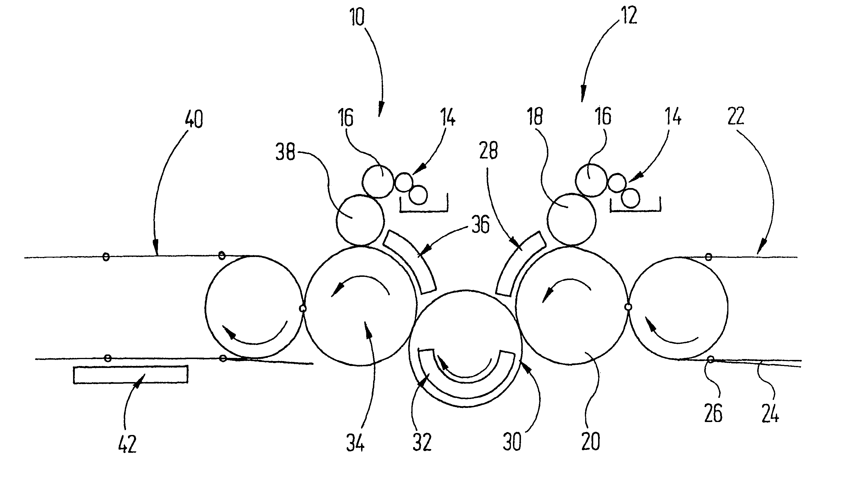
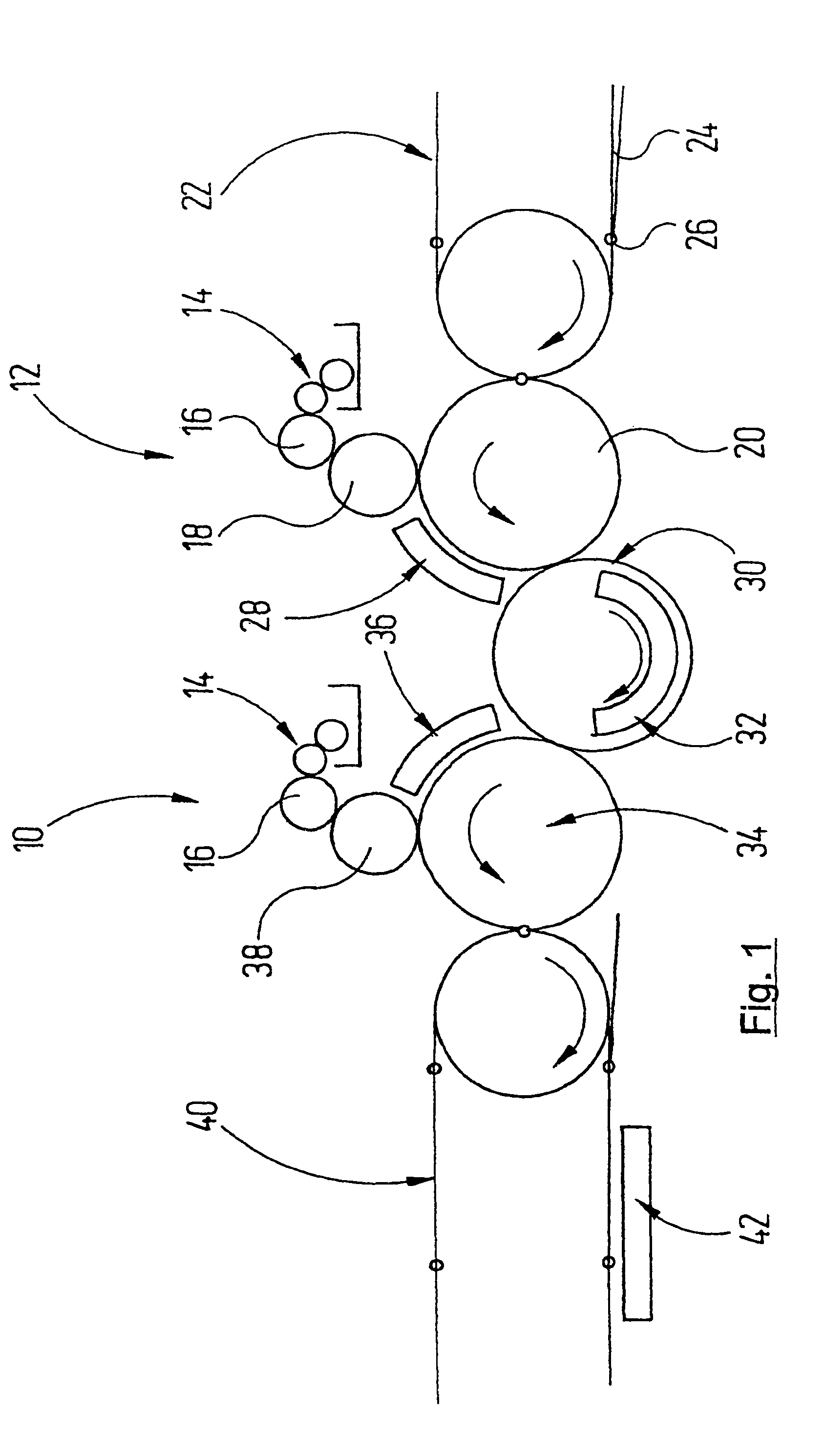
[0073]In FIG. 1 a detail is reproduced from a sheet-fed printing press that includes two printing towers 10, 12. Each of the printing towers has an inking unit 14 which provides ink to an application cylinder 16. The latter supplies an impression cylinder 18 which cooperates with a counter-cylinder 20.

[0074]A conveyor22, indicated schematically, carries individual printed sheets 24 to the counter-cylinder 20 using grippers 26. Said counter-cylinder accepts the printed sheets with its own grippers and carries them past the impression cylinder 18. By this means, a layer of printing-ink is produced on the printed sh...


PUM


Abstract

A flat UV light source has a tight packing of UV light-emitting diodes (56) that are arranged in a matrix. These light-emitting diodes are cooled by cooling air flows (66) or by cooling water flows.

Description

RELATED APPLICATION[0001]This application claims the filing benefit of PCT Patent Application No. PCT / EP2005 / 003268, filed Mar. 29, 2005; which claims the benefit of German Patent Application No. 10 2004 015 700.6, filed Mar. 29, 2004; the contents of which all are incorporated herein by reference.TECHNICAL FIELD[0002]The invention relates to a flat UV light source with a supporting structure and with a plurality of UV light-emitting elements supported said supporting structure, characterised in that the UV light-emitting elements are light-emitting diodes and are arranged in a matrix.BACKGROUND OF THE INVENTION[0003]Flat UV light sources are used, inter alia, in the print industry, in order to dry UV-curable printing-inks. Dryers of such a type encompass mercury-vapour lamps. For the purpose of operating mercury-vapour lamps of such a type, expensive and bulky mains power packs are necessary, which have to provide a high igniting voltage a maintaining voltage. Mains power packs of ...

Claims


Application Information

Patent Timeline
Patent Type & Authority Patents(United States)
IPC IPC(8): A61N5/06H05G1/00G01J3/10B41F23/04F21K99/00F26B3/28H01L33/00
CPCF21K9/00F26B3/283F21V29/83F21V29/20F21V29/677B05D3/061
Inventor PLATSCH, HANS G.
Owner PLATSCH
Why Eureka
Try Eureka