Observation method of hypersonic internal flow-field wave structure

A hypersonic and internal flow field technology, which is applied in the testing of machines/structural components, measuring devices, instruments, etc., can solve the wave system structure and observation of the internal flow field that cannot be modeled, and the observation of the wave system structure of the internal flow field that cannot be modeled, etc. problems, to achieve the effect of rich and comprehensive flow field information, simple optical path layout, and low equipment requirements

Active Publication Date: 2017-05-31
CHINA ACAD OF AEROSPACE AERODYNAMICS
View PDF8 Cites 15 Cited by
  • Summary
  • Abstract
  • Description
  • Claims
  • Application Information

AI Technical Summary

Problems solved by technology

[0002] In conventional hypersonic wind tunnel tests, the schlieren method or the shadow method are generally used to display the wave system structure of the flow field around the model, but both the schlieren and shadow methods are based on the fact that the optical refractive index of the gas is a function of density. It is measured by the principle of light deflection. Since optical refraction is an integral process of a path, it is impossible to use the above two methods to observe the wave system structure of the flow field in the model, let alone to carry out the wave system structure of the flow field at different positions in the model. to observe

Method used


Image

  • Observation method of hypersonic internal flow-field wave structure
  • Observation method of hypersonic internal flow-field wave structure
  • Observation method of hypersonic internal flow-field wave structure

Examples


Embodiment Construction
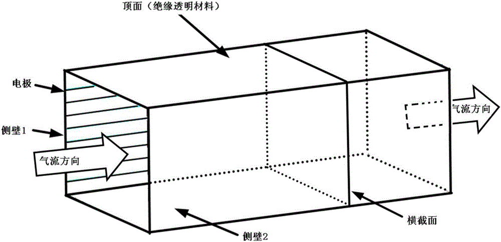
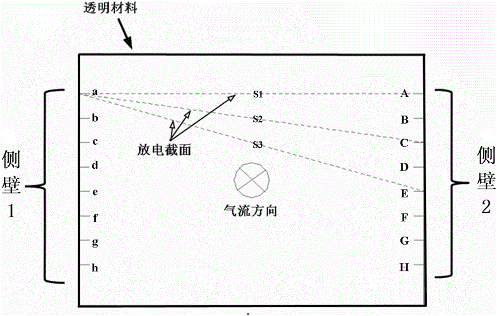
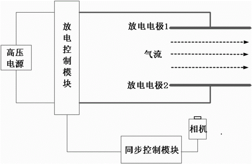
[0024] The basic idea of ​​the present invention is to propose a method for observing the wave system structure of the hypersonic internal flow field. This method is simple, feasible, low in construction cost, and obtains the wave system structure of the internal flow field in the model. It utilizes glow discharge The principle of flow field display technology is to observe the sub-section of the flow field wave system structure in the model. In the test, one side of the model is made of transparent materials to facilitate the shooting of glow discharge images, and multiple pairs of discharge electrodes are arranged on the opposite wall inside the model. , the discharge control unit is used to sequentially select one pair of electrodes for discharge, and the synchronization control unit is used to synchronize the glow discharge and camera shooting, so that multiple cross-sectional flow field wave structures can be obtained in one test. This method has a simple structure and low...


PUM


Abstract

The invention discloses an observation method of a hypersonic internal flow-field wave structure, particularly a method for obtaining a model internal flow-field wave structure, which is simple, feasible, and low in construction cost. The observation method utilizes theories of glow discharge flow-field display technologies to carry out partial cross-section observation on the model internal flow-field wave structure. In a test, one side of a model is made of a transparent material, so that glow discharge images are shot conveniently; a plurality of discharge electrodes are arranged on internal relative walls of the model, a discharge control unit is adopted for selecting a pair of the electrodes in sequence to discharge, and a synchronous control unit is adopted for synchronizing glow discharge and camera shooting, therefore, flow-field wave structures of multiple sections can be obtained in one test. The method has the advantages of simple structure and relatively low equipment requirements, and is a flow-field display method which can be used in hypersonic low-density wind tunnels.

Description

technical field [0001] The invention relates to a method for observing the wave system structure of a hypersonic internal flow field, which belongs to the field of wind tunnel flow field display. Background technique [0002] In conventional hypersonic wind tunnel tests, the schlieren method or the shadow method are generally used to display the wave system structure of the flow field around the model, but both the schlieren and shadow methods are based on the fact that the optical refractive index of the gas is a function of density. It is measured by the principle of light deflection. Since optical refraction is an integral process of a path, it is impossible to use the above two methods to observe the wave system structure of the flow field in the model, let alone to carry out the wave system structure of the flow field at different positions in the model. observe. Contents of the invention [0003] The technical problem to be solved by the present invention is to prov...

Claims


Application Information

Patent Timeline
Patent Type & Authority Applications(China)
IPC IPC(8): G01M9/06
CPCG01M9/06G01M9/067
Inventor 沙心国陈星纪锋文帅袁明论
Owner CHINA ACAD OF AEROSPACE AERODYNAMICS
Why Eureka
Try Eureka