A combined loading kinematic joint bearing testing machine

A joint bearing and combined loading technology, which is applied in the direction of mechanical bearing testing, etc., can solve the problem of not being able to truly simulate the bearing conditions of radial joint bearings, and achieve the effect of novel structure

Active Publication Date: 2019-04-16
中机思美迪(长春)科技有限公司
View PDF6 Cites 0 Cited by
  • Summary
  • Abstract
  • Description
  • Claims
  • Application Information

AI Technical Summary

Problems solved by technology

[0003] The invention provides a combined loading motion joint bearing testing machine to solve the problem that the current domestic radial joint bearing testing machine is mainly loaded in the axial and radial directions, and cannot truly simulate the bearing situation of the radial joint bearing.

Method used


Image

  • A combined loading kinematic joint bearing testing machine
  • A combined loading kinematic joint bearing testing machine
  • A combined loading kinematic joint bearing testing machine

Examples


Embodiment Construction

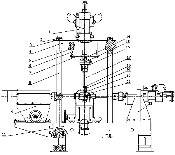
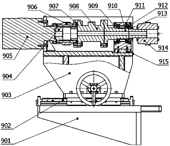
[0021] The fixture tooling 21 is fixed on the workbench 11 by bolts, the lateral torsion mechanism 9 is fixedly connected to the left end of the workbench 11 by screws, the axial loading mechanism 22 is fixedly connected to the right end of the workbench 11 by bolts, and the lateral swing mechanism 31 is connected to the workbench by screws. The rear end of the table 11 is fixedly connected; the four columns 8 are installed on the upper surface of the workbench 11, and are fixed and locked with the workbench 11 through the column back nut 3 and the column back nut 2, and the connecting beam 4 is installed on the upper end of the column 8 , and fixed and locked with the workbench 11 through the column back nut 3 and the column small back nut 2, the oil cylinder one 1 is fixedly connected with the upper end of the crossbeam 4 through screws, and the transverse torsion mechanism 9 expands with the left end of the fixture tooling 21 through the coupling one 914 Tightly and fixedly ...


PUM


Abstract

The invention relates to a combined loading motion joint bearing testing machine, and belongs to the technical field of bearing test detection. A clamping tool is fixed on a workbench through a bolt; a transverse torsion mechanism is in fixed connection with the left end of the workbench through a screw; an axial loading mechanism is in fixed connection with the right end of the workbench through a bolt; a lateral swing mechanism is fixedly connected with the rear end of the workbench by a screw; four columns are mounted on the upper surface of the workbench; a connecting beam is mounted on the upper ends of the columns; and a first oil cylinder is fixedly connected with the upper end of the beam through a screw. The combined loading motion joint bearing testing machine is advantaged in that the structure is novel; a swing actuator and a linear actuator as executing power elements realize axial and radial loading and revolution and inclined swinging; synchronous and asynchronous coordinated operation can be performed so as to simulate loaded and moving states of a centripetal joint bearing, detect and display the load, the friction coefficient, the wear extent, the temperature, the number of movements, the time and the sliding distance in real time and can simulate the working environment of the sample bearing in a real mode.

Description

technical field [0001] The invention belongs to the technical field of bearing testing and detection, and mainly relates to a testing machine for kinematic joint bearings. Background technique [0002] As an important part of sliding bearings, radial joint bearings are widely used in aerospace, rail cars, mines, metallurgy, heavy vehicles, water conservancy and hydropower and other fields. It consists of an outer ring with an inner spherical surface, an inner ring with an outer spherical surface and Padded composition. During use, the radial spherical plain bearing mainly bears radial load, axial load, rotary swing, and lateral swing. The wear of the bearing liner is an important factor leading to the failure of the radial spherical plain bearing. The cause of the wear of the liner is opposite The research on radial spherical plain bearings plays a vital role. At present, the radial spherical plain bearing testing machines in China are mainly loaded in the axial and radial ...

Claims


Application Information

Patent Timeline
Patent Type & Authority Patents(China)
IPC IPC(8): G01M13/04
CPCG01M13/04
Inventor 魏仁杰马伟张再林杨秀光
Owner 中机思美迪(长春)科技有限公司
Why Eureka
Try Eureka