Rotatable support mechanism of thermal load test bench

A technology of support mechanism and test bench, which is applied in engine testing, machine/structural component testing, measuring devices, etc., can solve the problems of low cooling efficiency, unsightly appearance, inaccurate simulation of component temperature field distribution, etc. The effect of crack identification, easy inspection, and simple arrangement of cooling channels

Inactive Publication Date: 2017-05-31
CHINA NORTH ENGINE INST TIANJIN
View PDF6 Cites 1 Cited by
  • Summary
  • Abstract
  • Description
  • Claims
  • Application Information

AI Technical Summary

Problems solved by technology

[0003] At present, there are mainly the following problems in the support mechanism of the test bench in the thermal load test: 1) Generally, the test pieces are installed on a fixed test bench with the assessment site facing upwards, and the heater (including: laser, electromagnetic induction coil, flame burner etc.) to heat the assessment part of the test piece. After heating the test piece, the heated airflow flows away in the opposite direction, which cannot scour the air passage. As a result, only the local temperature of the fire surface of the test piece meets the requirements, while the overall temperature field There is a large difference between the distribution and the state of the whole machine, and there is also the problem that the fire surface of the cylinder head under the state of the whole machine and the oxidation corrosion damage of the air passage in the gas environment cannot be accurately simulated; 2) The current fixed test support table leads to It is inconvenient to check the cracks in the part of the test piece or it is difficult to take pictures with the camera equipment; 3) The current cooling method of the test bench generally uses compressed air to spray the fire surface, and the cooling efficiency is not high, and the simulation of the temperature field distribution of the components is not accurate. There are problems such as chaotic layout of water pipes and unsightly appearance

Method used


Image

  • Rotatable support mechanism of thermal load test bench
  • Rotatable support mechanism of thermal load test bench
  • Rotatable support mechanism of thermal load test bench

Examples


Embodiment Construction

[0023] It should be noted that, in the case of no conflict, the embodiments of the present invention and the features in the embodiments can be combined with each other.

[0024] The present invention will be described in detail below with reference to the accompanying drawings and examples.

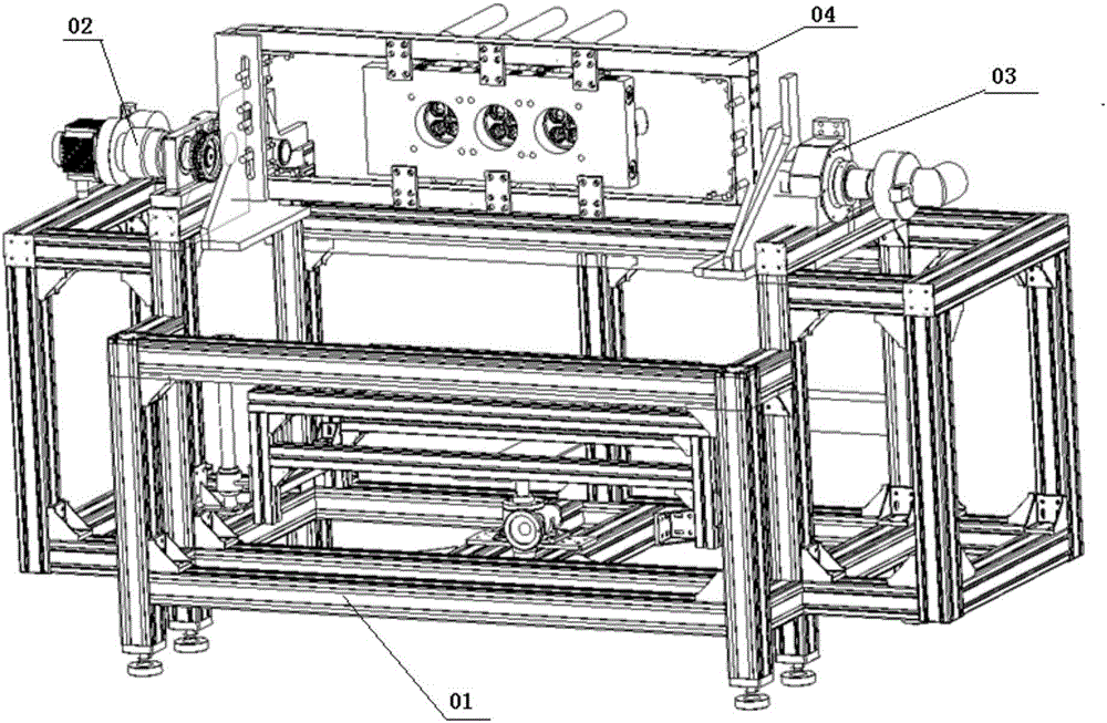
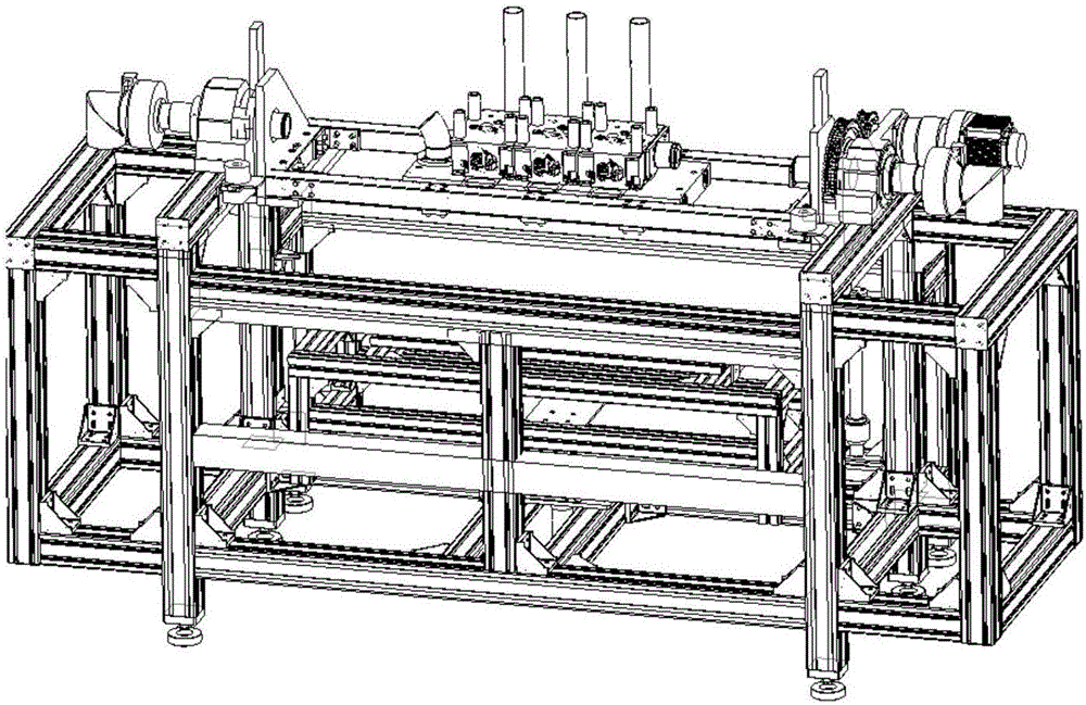
[0025] A rotatable thermal load test bench support mechanism such as figure 1 , 2 As shown, it includes a test bench main frame 01, a test bench rotation support mechanism, and a support frame 04. The test bench rotation support mechanism includes a left rotation support mechanism 02 and a right rotation support mechanism fixedly installed on the left and right sides of the upper surface of the test bench main frame, respectively. The supporting mechanism 03, the left-rotating supporting mechanism and the right-rotating supporting mechanism are respectively fixedly connected to the two ends of the supporting frame, and play the role of supporting and turning over the supporting frame. ...


PUM


Abstract

The invention provides a rotatable support mechanism of a thermal load test bench. The rotatable support mechanism comprises a test bench main body framework, a test bench rotation support mechanism, a support framework and a cooling water supply mechanism. The test bench rotation support mechanism comprises a left rotation support mechanism and a right rotation support mechanism which are respectively fixedly installed on left and right sides of the upper surface of the test bench main body framework. The left rotation support mechanism and the right rotation support mechanism are fixedly connected with two ends of the support framework respectively. According to the invention, thermal fatigue testing of different to-be-tested pieces can be achieved; through exchange of the support framework, support for to-be-tested pieces of a cylinder cover and a piston can be achieved, and test requirements of to-be-tested pieces with different cylinder diameters can be also achieved; through the overturn function, it can be achieved that during a test, the thermal power of the to-be-tested piece id downwards, and the combustion flame is upwards, and it can be achieved that after the thermal power of the to-be-tested piece is backwards, the gas upwards washes an air flue, and comprehensive and real simulation of working states of the to-be-tested piece can be achieved; and it can be achieved that cooling water is provided through a rotation shaft.

Description

technical field [0001] The invention belongs to the technical field of thermal load test devices, and in particular relates to a rotatable thermal load test bench support mechanism. Background technique [0002] The heat load of the key structural parts of the engine combustion chamber, such as the piston and the cylinder head, is getting higher and higher. It is particularly necessary to check and evaluate the ability of the piston and the cylinder head to withstand the heat load in the engine design stage. The damage of piston and cylinder head during engine operation mainly includes fatigue damage at high temperature, creep damage and oxidation corrosion damage under gas environment. Current piston and cylinder head thermal load tests mainly include laser heating, electromagnetic induction heating and gas heating. [0003] At present, there are mainly the following problems in the support mechanism of the test bench in the thermal load test: 1) Generally, the test pieces...

Claims


Application Information

Patent Timeline
Patent Type & Authority Applications(China)
IPC IPC(8): G01M15/02
CPCG01M15/02
Inventor 许春光卫军朝李鹏文洋王小慧景国玺马宁王根全
Owner CHINA NORTH ENGINE INST TIANJIN
Why Eureka
Try Eureka