An Ultrasonic Visual Imaging Method for Detecting Composite Structural Rib Area

A technology of composite materials and structural ribs, which is applied to the analysis of solids using sound waves/ultrasonic waves/infrasonic waves, and can solve the problems of poor real-time verification of test results, influence of subjective factors by testers, and low test efficiency.

Active Publication Date: 2019-10-18
AVIC COMPOSITES
View PDF6 Cites 0 Cited by
  • Summary
  • Abstract
  • Description
  • Claims
  • Application Information

AI Technical Summary

Problems solved by technology

At present, the non-destructive testing of the rib structure of composite materials is based on the ultrasonic method: one is to use the manual ultrasonic scanning method, and use the ultrasonic A-display signal for defect discrimination. The main disadvantages are: (1) point scanning, low detection efficiency, It is easy to miss inspection; (2) The inspection results cannot be visualized and imaged, which may easily lead to misjudgment of defects; (3) It is difficult to display the global display of the detected rib area in real time; (4) The defect identification is easily affected by the subjective factors of the inspectors
In order to improve its shortcomings, another detection method is to design some special ultrasonic automatic scanning detection systems to realize the scanning and imaging detection of the structural parts of composite ribs. The main disadvantages are: (1) the cost is very high and the technology is difficult , it is necessary to design different scanning detection systems according to the geometric characteristics of the structural parts of the ribs of different composite materials; (2) Due to the complexity of the automatic scanning mechanism and the limitation of the environmental conditions of the site, it is difficult to realize; (3) The requirements for the detection site are high , needs to occupy a large dedicated testing site; (4) The verification of the test results is not real-time

Method used


Image

  • An Ultrasonic Visual Imaging Method for Detecting Composite Structural Rib Area
  • An Ultrasonic Visual Imaging Method for Detecting Composite Structural Rib Area
  • An Ultrasonic Visual Imaging Method for Detecting Composite Structural Rib Area

Examples


Embodiment

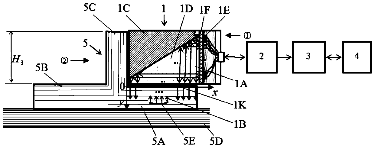
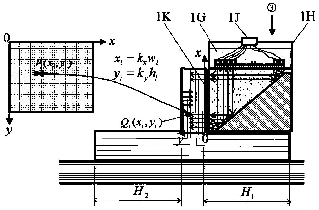
[0142] Adopt the patent of this invention, choose the UBZ-1 series ultrasonic array transducer of AVIC Composite Materials Co., Ltd. and its supporting ultrasonic array unit, signal processing unit and display unit, use water as contact and non-contact coupling agent A series of actual detection applications have been carried out on different parts of the rib area of ​​the material structure. Among them, the frequency of the transducer is 5MHz, 7.5MHz and 10MHz. The width of the rib area ranges from 20mm, 40mm, and 80mm. The series of actual test application results show that it can effectively detect the defects of Ф3mm and the delamination of Ф6mm and the pores of the glue layer in different parts of the rib area of ​​the composite structure As well as the structural changes in the rib area, etc., the visual imaging quality is very clear, and a good actual detection effect has been achieved.


PUM


Abstract

The invention belongs to the technical field of nondestructive detection and relates to an ultrasonic visual imaging method for detecting composite structure stiffener zones. On the basis of an ultrasonic reflection principle, a rapid ultrasonic scanning visual imaging method is established by selecting an ultrasonic reflector array linear scanning array transducer to realize rapid ultrasonic scanning visual imaging detections of different parts of the composite structure stiffener zone; through selecting different scanning modes and incident directions as well as the array transducer, ultrasonic visual imaging detections of different composite structure stiffener zones are realized. The actual detection effect shows that the visible degrees, defect detection rates and detection efficiencies of ultrasonic detections of the different parts of the composite structure stiffener zone are obviously enhanced; phi 3mm layering in the different parts of the composite structure stiffener zone can be detected; the visible imaging quality is very clear and a very good actual detection effect is achieved.

Description

technical field [0001] The invention belongs to the technical field of non-destructive testing, and relates to an ultrasonic visualization imaging method for detecting rib areas of composite material structures. Background technique [0002] Various composite reinforcement ribs are an important part of the composite material load-bearing structure, which play a role in load transmission and load-bearing in the composite material structure. This composite material structure has been used in aerospace, transportation and other industrial fields. widely. Reliable non-destructive testing of structural parts of composite ribs is often required. At present, the non-destructive testing of the rib structure of composite materials is based on the ultrasonic method: one is to use the manual ultrasonic scanning method, and use the ultrasonic A-display signal for defect discrimination. The main disadvantages are: (1) point scanning, low detection efficiency, It is easy to miss detecti...

Claims


Application Information

Patent Timeline
Patent Type & Authority Patents(China)
IPC IPC(8): G01N29/06
Inventor 刘菲菲刘松平李治应李乐刚傅天航史俊伟
Owner AVIC COMPOSITES
Why Eureka
Try Eureka