Optical pump magnetometer gradient tolerance measuring device

A technology of optical pump magnetometer and measuring device, which is applied to measuring devices, measuring electrical variables, instruments, etc., can solve the problems of undisclosed testing methods and devices, and achieve the effect of high degree of automation and simple operation.

Active Publication Date: 2017-05-31
THE 715TH RES INST OF CHINA SHIPBUILDING IND CORP
7 Cites 4 Cited by

AI-Extracted Technical Summary

Problems solved by technology

Dmitry Budker of Cambridge University's book "Optical Magnetometry" mentioned the definition of the grad...

Abstract

The invention provides an optical pump magnetometer gradient tolerance measuring device. The optical pump magnetometer gradient tolerance measuring device mainly comprises a horizontal base, a gradient generating coil, a horizontal connecting rod, bubble levels, a connecting rod leveling device, an optical pump probe mounting clamp, a laser range finder, a precise current source and a measuring and control module, wherein the measuring and control module calculates the magnitude of currents which need to be output to generate a specific magnetic gradient according to preset parameters such as the probe position, probe size, coil turn number and coil radius and controls the precise current source through a USB interface to output specific currents to the gradient generating coil; the gradient generating coil is mounted on the horizontal base, the position of the gradient generating coil is adjusted through the bubble level A, and the gradient generating coil generates the magnetic gradient in a surrounding space; the optical pump probe mounting clamp is arranged on the horizontal connecting rod, and the horizontal connecting rod is regulated through the bubble level A, the bubble level and the connecting rod leveling device to be parallel with the axis of the gradient generating coil.

Application Domain

Electrical measurements

Technology Topic

PhysicsLaser ranging +9

Image

  • Optical pump magnetometer gradient tolerance measuring device
  • Optical pump magnetometer gradient tolerance measuring device
  • Optical pump magnetometer gradient tolerance measuring device

Examples

  • Experimental program(1)

Example Embodiment

[0014] The present invention will be described in detail below in conjunction with the drawings:
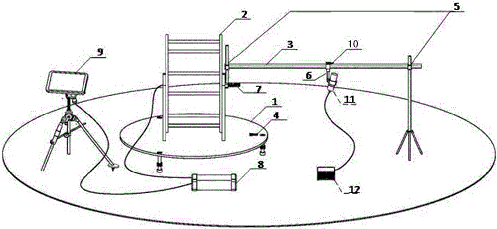
[0015] The optical pump magnetometer gradient tolerance measuring device of the present invention mainly includes a horizontal base 1, a gradient generating coil 2, a horizontal connecting rod 3, a bubble level 4, a connecting rod level adjusting device 5, and an optical pump probe installation fixture 6 , Laser rangefinder 7, precision current source 8, and measurement and control module 9. The measurement and control module 9 calculates the output current required to generate a specific magnetic gradient according to preset parameters such as probe position, probe size, coil turns, and coil radius, and passes The USB interface controls the precision current source 8 to output a specific current to the gradient generating coil 2. The gradient generating coil 2 is installed on the horizontal base 1 and the position is adjusted by the bubble level A4. The gradient generating coil 2 generates a magnetic gradient in the surrounding space; on the horizontal connecting rod 3 Equipped with the light pump probe installation fixture 6, and adjust the horizontal connecting rod 3 to be parallel to the axis of the gradient generating coil 2 through the bubble level A4, the bubble level B and the connecting rod level adjustment device 5; the light pump probe 11 to be measured and the magnetometer host to be measured 12 Connect and install it in the optical pump probe installation fixture 6 (the optical pump probe installation fixture 6 can be adjusted by the probe position adjustment device), and measure the distance from the center of the gradient generating coil 2 to the optical pump probe 11 to be measured by the laser rangefinder 7 . The measurement and control module 9 includes the number of coil turns N, the coil radius R, the area C (OA, r, OB) where the probe is located, and the set gradient value dT according to the input parameters. 0 , The output parameters include the output current I, the actual gradient range dT in the area C 0 , DT 1 , And finally ensure that the minimum actual magnetic gradient in area C is greater than or equal to dT 0.
[0016] figure 1 Among them, the optical pump probe 11 to be tested and the host 12 of the magnetometer to be tested are the optical pump magnetometers to be tested. The horizontal base 1 completes the horizontal fixation of the gradient generating coil 2, the connecting rod level adjustment device 5, the bubble leveler ensures that the horizontal connecting rod 3 is in the horizontal plane and the coil axis is parallel, the optical pump probe installation fixture 6 completes the installation of the optical pump probe 11 to be measured, laser The distance meter 7 completes the distance measurement from the center of the coil to the optical pump probe 11 to be measured. The measurement and control module 9 calculates the output current required to set the magnetic gradient according to preset parameters such as probe position, probe size, coil turns, and coil radius. , And control the precision current source 8 to output a specific current through the USB interface to ensure that the minimum value of the magnetic field gradient in the area where the optical pump probe 11 to be measured is located is greater than the set magnetic gradient.
[0017] figure 2 Implement steps for gradient tolerance measurement. Among them, the measurement preparation completes the connection of the relevant instruments; the level adjustment of the base can ensure that the axis of the coil is on the horizontal plane; the level adjustment of the connecting rod ensures that the connecting rod is on the horizontal plane and parallel to the axis of the coil; after fixing the probe on the fixture, adjust the laser measurement From the light point of the instrument to the probe, record the distance from the center of the coil to the probe. The measurement and control module 9 can calculate the output current required to generate a specific magnetic gradient according to preset parameters such as the number of coil turns N, the coil radius R, and the area where the probe is located (OA, r, OB), and control the output of the precision current source 8 through the USB interface Specific current I; after generating a given magnetic field gradient, check the working status of the magnetometer. If it works normally, increase the gradient and observe the working status of the magnetometer again. If it works abnormally, the last set magnetic field gradient value will be waiting Gradient tolerance of the magnetometer.
[0018] image 3 Calculate the model for the magnetic gradient. Taking the center O of the coil as the origin of the coordinates, the axis direction is Z, the vertical direction is X, and the horizontal direction is Y. When the number of coil turns is N, the coil radius is R, and the supply current is I, the Biot-Savart law The magnetic field vector at any point (x, y, z) in space can be calculated for,
[0019]
[0020] Among them, μ 0 Is the permeability in vacuum, and θ is the integral independent variable around the coil.
[0021] The gradient of the total field B along the Z direction in the area where the probe is located The minimum gradient generated is
[0022]
[0023] Figure 4 It is a diagram of the input and output parameters of the measurement and control software. The input parameters of the measurement and control software include the number of turns of the coil N, the radius of the coil R, the area C (OA, r, OB) where the probe is located, and the set gradient value dT 0 , The output parameters include the output current I, the actual gradient range dT in the area C 0 ~dT 1 , And finally ensure that the minimum actual gradient in area C is greater than or equal to dT 0.
[0024] It can be understood that for those skilled in the art, equivalent replacements or changes to the technical solutions and inventive concepts of the present invention should fall within the protection scope of the appended claims of the present invention.

PUM

no PUM

Description & Claims & Application Information

We can also present the details of the Description, Claims and Application information to help users get a comprehensive understanding of the technical details of the patent, such as background art, summary of invention, brief description of drawings, description of embodiments, and other original content. On the other hand, users can also determine the specific scope of protection of the technology through the list of claims; as well as understand the changes in the life cycle of the technology with the presentation of the patent timeline. Login to view more.

Similar technology patents

Laser radar optical system with optical axis calibrating function and optical axis calibrating method

InactiveCN102353950AOptical axis alignment with high precisioneasy to operate
Owner:INST OF APPLIED ELECTRONICS CHINA ACAD OF ENG PHYSICS +1

Defrosting control method and device

ActiveCN104807132Aeasy to operateDefrost is reasonable
Owner:GREE ELECTRIC APPLIANCES INC OF ZHUHAI

Classification and recommendation of technical efficacy words

  • easy to operate
  • high degree of automation

Lancet device

InactiveUS7303573B2inexpensively mass-producedeasy to operate
Owner:ABBOTT DIABETES CARE INC

Rapid and non-invasive optical detection of internal bleeding

InactiveUS20050065436A1easy to operaterapid and accurate result
Owner:HO WINSTON ZONH +2

High-fineness urban three-dimensional modeling method

Owner:星际空间(天津)科技发展有限公司

Bolt machining all-in-one machine

Owner:ANHUI LIUFANG ZHONGLIAN MECHANICAL SHARE
Why Eureka
Try Eureka